Design:Seam algebra(for drawing)
Contents
Some measurements need to be performed on drawing elements in the course of work.
The system allows taking measurements of lines (segments, arcs, any curves), parts of lines, distances between points along the straight line, on projection of the distance onto the X or Y axis, and display results of these measurements.
The “Seam Algebra” measurement panel is located in the bottom horizontal area of the screen.


Box displaying measurement resultsMeasurement command buttons
Box displaying lengths of measured lines
These buttons can be used to make the following measurements:
-
 and
 buttons allow commencing the measurement operation by selecting the required sign and then one of the measurement command buttons
-
 button allows making measurements of the entire line. You can measure any line, except the working straight line passing through the whole screen (the grey dashed line)
-
 button allows measuring the part of the line between two specified points located on this line
-
 button allows making measurements between any two points along the straight line.
-
 and
 buttons allow determining the projection of the measured distance between two points onto the X or Y axis.


The left part of the “Seam Algebra” comprises buttons of commands intended for working with obtained measurement data (for the size which is on the screen when working with the project)

 button clears the measurement window. The measurement values which have already been viewed, need to be deleted using this button (to prevent them from affecting the results of new measurements made by you).
 button allows deleting only selected values from the measurement window, instead of all. This button is useful when you need to eliminate a mistake made during measurements. The erroneously measured value is selected by clicking the mouse button on it and is deleted by pressing this button.
 button allows viewing result of particular measurements for other size, height and width displayed.
Measurement Functions for Working With Drawings
Measuring Line Length
 In order to measure the length of any line entirely:
- Press
 button. The cursor will take the form of
 .


( button is activated automatically when this button is selected, therefore, you do not have to press it in this case. However, if another measurement command has been used before this measurement (for example, [[Image:]] ), this command needs to be selected.)
- Set the cursor crosshair on the line to be measured and click the mouse left button. The measured line will be colored red.
- The measurement result for the size on the screen will be displayed in the table left box.
Measuring Part of Line Between Points

In order to measure the length of the line part between two points of the line:
- Press
 button, then
 . The cursor will take the form of
 .
- Click at the point on the line (1), then on the line itself (2), and then at the second point of the same line (3) in random sequence. The part of the line between the specified points will be measured (this part will be colored red).
- The measurement result for the size on the screen will be displayed in the table left box.


Measuring Distance Between Two Points Along Straight Line
In order to measure distance between any two points along the straight line:
- Press
 button, then
 . The cursor will take the form of
 .


- Click with the cursor crosshair at one point (1) and then click with the cursor crosshair on the other point (2). A red straight line will be drawn between the points (1) and (2) to show the measured parameter.
- The measurement result for the size on the screen will be displayed in the table left box.

Measuring Projections of Distance Between Points Onto X or Y Axes
In order to determine the projection of the measured distance between two points onto the X axis:
-
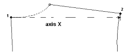 Press
 button, then
 . The cursor will take the form of
 .
- Click with the cursor crosshair at one point (1) and then click with the cursor crosshair on the other point (2). A red straight line will be drawn between the points (1) and (2) to show the measured parameter.


- The measurement result for the size on the screen will be displayed in the table left box.
- The function of measuring the projection onto the Y axis is identical to that described above with the only difference that
 button needs to be used.


Checking Line Length Ratio
In order to check the ratio of lengths of different lines, measure the length of one line with the “+” sign, and the other one with the “-“ sign.
Consider the following example. You need to measure the ratio of the shoulder lengths of the front and back in the drawing.

In order to do this:
- Press
 and
 buttons successively. The cursor will take the form of
 ; (you do not have to select
 button because it is automatically set when entering the addition (
 ) or subtraction (
 ) mode).
- Click with the cursor crosshair on the line of the segment (1) in the back drawing. The length of the seam between these two points will be displayed in the table left box with the plus sign;
- Press
 button. The cursor will take the form of
 ;
- Click with the cursor crosshair on the line of segments (2) and (3) on the front successively.


The lengths of the segments of the second piece with the “-” sign will be added in the table left box.
The measurement result for the size on the screen will be displayed in the table left box as the difference between two segments with regard to the sign.


If the Size Base has been used for the project, it may be necessary to view the result of the same measurement in another size. To do this:
- Display the project drawing in the required size/ height/ width.
In order to do this, take the following actions:
Press button (initial data) of the button menu to enter the project initial data table. A data input table will be displayed on the screen:

Use the boxes for size selection to display the required size, height or width:

The data from the base are filled in when  button in the upper right corner of the table is pressed. Then press the “Yes” button to confirm the selection.
- In order to display the drawing of the required size, select
 button in the left button menu of the program.
- In order to see the result of the measurements made in this size, press the button of result recalculation (
 ) (without deleting the measurement data with
 button). Now, data for the new size will be recorded in the result box.


