Constructor:piece parameters
To change piece characteristics (material, number, name, etc.):
- Select PIECE tab and the button
 in the tab. The cursor will be changed to


You can also follow the text menu points “Piece/ Parameters”.
- Specify the piece. The parameter window for a given piece is displayed on the screen.
- To change the piece parameters, make changes in the corresponding window cell.
The parameters Material, Name and Number of cut pieces are compulsory to fill in.
ATTENTION!
When pieces are named, their parameters are automatically set from “Utilities” program.
The parameters for a specific given piece must be checked and changed

To save changes in the parameters, press the YES button. The following inquiry will be displayed on the screen:

To confirm the data, press the YES button. To cancel changes, press the NO and CANCEL buttons.
List of piece parameters
 - Material (40 characters). Sorting pieces by materials allows to sort them by fabric type for layout (Top, Lining, Fusing fabric,…). With pressing the button
 , you can select a necessary material from the existing list, compiled in “Utilities” program.


 - Groups of piece names (40 characters) divide the general list of names for a more convenient selection. For example, “Top” group includes piece names of the top, “Fusing” group includes pocket facing, “Auxiliary” group includes pocket outline.

The name of the group can be input manually, or selected from the list compiled in “Utilities” program with pressing the button  . The group of piece names is selected automatically upon selection of material, if they have the same name.
 -Piece name (40 characters). With pressing the button
 , you can select a name from the list compiled in “Utilities” program. The existing names of the pieces are saved in the list and they can be selected later instead of inputting them again. When selecting pieces from the list, you can type the first letter or several letters, and the program will sort the pieces according to the mask, performing an automated search of the name by text match.

FEATURES
1) One material cannot have two pieces with the same name
When naming a piece existing in a given material, the following message is displayed on the screen:

YES button:- delete the piece with the same name and replace it with a new piece.
The replaced piece is automatically moved to “Deleted pieces” list of the window “Work with the database”.
Button NO cancels renaming.
2) Different materials can have pieces with the same name.
For example, the materials of Top, Lining, and Fusing can have pieces with the same name - Front. In this case the group of piece names can correspond to the assortment, not the material: Shoulder group (Front, Back, Sleeve); Waist group (Front trousers, Fly).
There is a different option for naming pieces: create a group of names of the same name for each material, where all piece names have their own beginning symbol. For example, in the group of names Top, all the names start with the letter T (T Front, T Back etc.).In the group Lining they start with letter L (L Front, L Back)
3) If manually change the piece name to the name already existing in a different Group, the Group of names for this piece will be automatically replaced (it is displayed upon the next opening of “Piece parameters” window).
 - Brief name of the piece in the layout (8 characters) (the cell next to the window with the Piece Name is not compulsory to fill in). It is assigned to a specific piece name in “Utilities” program and used for special marking of the piece in the specification and the layout (for example, to differentiate top and bottom collar – TC and BC).


 -The number of pieces in the layout per an item. With pressing the button
 , you can set a necessary value in the cell or input it manually. Displayed by default is the value set for a given piece name in “Utilities” program.


 - Code name of the piece (40 characters). The cell is not compulsory to fill in.

When converting pieces from other formats in “Converter” program, the cell is automatically filled in with a code meaning of the piece in the initial format. You can fill in the Code cell manually (in production of men's suits coding of the pieces used in different models, is used, etc.).
FEATURES
1) To work with the code you need to switch on the setting “Utilities”, otherwise the Code cell will not be displayed (GLOBAL SETTINGS/ General tab):

2) The code cell is cleared when performing different functions for creation of untitled pieces (PIECES tab 
 MODELING

 and CONTOUR
 .
3) When copying pieces in the window “Work with the database” the code is saved.
4) To send the piece code to print, you need to select a corresponding option in the specification (the text menu points “Setting/ Program parameters”, GENERAL/ Constructor tab

 - Types of piece grading: by sizes, heights, widths. It is not compulsory to switch off grading types. It clears the piece by a given criterion, repeating the piece shape of a basic size without special input of zero increments.

For example, when creating a piece with a macrocommand, one basic size is created. To create an ungraded piece you can automatically get a full gradation with switching off all the options in this setting. If the piece is only graded by sizes (Collar, etc.), you can deselect grading by heights. At the same time the piece shape in different heights will repeat the shape of corresponding sizes in the basic height without additional input of zero increments by height.
ATTENTION! If yet you need to grade a piece by size, height or width, prior to grading switch on the grading type which was switched off.
A special marking will be displayed next to the piece with switched off grading parameters in the list of pieces of the window “Work with the database”: first position – S (sizes), second position – H (heights), third position – W (width - filled only if widths are available). A zero is displayed in the place of the type switched off.
For example, for a piece not graded by sizes or heights: 00 (for a model incl. width: 000)
For a piece, only graded by sizes: S0 (for a model incl. width: S00 or S0W)
For a piece, only graded by heights: 0H (for a model incl. width: 0H0 or 0HW).
 - Piece types. Main piece is a piece, with which you can work all the programs of Julivi system. Auxiliary piece is a piece, which is only meant for Constructor program. These are working constructor’s pieces, which will not be displayed in the list of pieces in other programs (for example, these pieces will not be displayed in “Marker” program).

 - Versions of a piece within the model. This parameter is not compulsory for work. 0 option is set by default for all the pieces.
If necessary, you can input several versions of the piece within one model.
For example, a trouser model has two versions of a belt: with a grain line along the belt (for striped fabrics) and across the belt (for smooth fabrics). For one belt (“Belt 1”) version 1 is set, for another (“Belt 2”) version 2 is set. For all other pieces, common for both options, version 0 is set by default.
Selection of a necessary option for a given fabric code is done in “Marker” program:
Version 1: all pieces with version 1 and common pieces with version 0;
Version 2: all pieces with version 2 and common pieces with version 0.  - Name of basic model and piece. The cells are filled in automatically, depending on how the piece was created. In general case, the cells are not filled in.
1) If the piece was copied from a different model as a reference piece in the window “Work with the database” (without an option to correct it, i.e. actually available in the basic model). The code of the basic model and the name of the basic piece will be input in the cells. Deselection of a check mark in “Unified” cell cancels connection with the basic model and allows to work with a given free piece.


2) If a piece was input from “Designer” program (the function  - “Piece/ Perform a project”), these cells will have the name of the project and the name of the basic piece.

The line for a unified piece in the window “Work with the database” will have letter U, and the line for a piece, opened from “Designer” program will have letter D.  - cells for Parameters of rough pieces of “Marker” program: values of allowance growing, notches and drawing.
You can make a rough piece in different ways: in “Marker” program or “Constructor” program changing the piece shape with the help of seam allowance, or by means of setting parameters for a rough piece.
To create rough pieces in “Piece parameters” window:
- Switch on the option “Draw in lay: Rough piece”. The bloc “Parameters of rough piece” is activated
- Set an increment value in the windows “Along the grain line” and “Across the grain line” in working measurement units (when negative increment values are input, it is possible to create a piece for interlining fabric with cutting a piece all around inside the contour)
- The option “Notches on rough piece” determines whether notches will be drawn in the layout

When the option “Draw in lay: Piece” is off, only contour of the rough piece will be drawn in the layouts. When the option is on, 2 contours will be displayed at the same time: one of a piece, and one of a rough piece.
The piece view does not change on the screen, but is transferred to “Marker” program with a set increment.
Letters RP will be displayed in the line for the piece with the parameter “Draw in lay: rough piece” in the list of pieces of the window “Work with the database”. Letters PRP will be displayed in the line for the piece with the parameter “Draw in lay: piece and rough piece”.
Letter X will be displayed in the line for the piece with switched off drawing of notches, but the setting “Notches on rough pieces” only works if the general option for drawing  is not switched off
FEATURES When an arbitrary contour is created (the command  - “Contour/ Create a new contour) you can draft the contour Direction line for a rough piece on a piece in order to set direction for growing allowances of the rough piece created in “Piece parameters” window.

For example, in the gorge piece made for pieceed fabric grain line is directed angularly, while in its interlining lining it is directed across the piece.

You can create rough pieces for both these pieces in “Piece parameters” window, but their shape will not be the same in the layout, because the rough pieces will be increased with reference to grain lines of different directions:

To solve this problem, you can create a contour Direction line for a rough piece by two central points on the shell piece. This line matches the direction of the grain line on the interlining lining piece, so increasing allowances in rough pieces will be the same for both pieces.

 - bloc for setting Grain line parameters for the layout.
Admissible deviation limits the deviation value of the grain line in the layout. When deviation is input, 2 lines are displayed on the piece next to the grain line, and their slope corresponds to a set value.
For example, when deviation of the grain line for the front lining is set at 2 degrees, the piece looks the following way:

Deviation in degrees or percentage is set in “Utilities” program in the tab GLOBAL SETTINGS/Linear approximation, grain line, specification.
Here you can also set a default value for admissible deviation:

- The setting
 Change of grain line direction for pairs of pieces is off in general case, i.e. pairs of pieces have the same direction of the grain line (nap). Switching on this parameter (YES button) is necessary to rotate pairs of pieces along the horizontal axis, instead of the vertical axis. For example, such rotation of pieces in the layouts for fabrics with asymmetrical piece will allow to keep the pieces symmetrical.


 - Piece orientation in “Constructor” program.

You can select a working mode with the pieces on the screen convenient for the constructor, once for the entire duration of work: Face up or down, and not change it depending on the lay type in “Marker” program.
The selected type is marked with letters U or D in the lines of the piece list in “Work with the database” window.
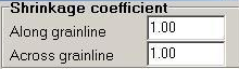 - Shrinkage parameters allow to increase (decrease) the piece size across and along the grain line in the layout for shrinking (or stretch) fabrics. For example, if you input a coefficient 1.02 along the grain line, the piece will be increased by 2 % in length in the layout.

The letter C is displayed in the line for pieces with a set coefficient in the “Work with the database” window.
FEATURES 1) Common percentage for material shrinkage can be set in “Marker” program, and for separate pieces with different shrinkage you can set a coefficient taking into account the difference in shrinkage.
2) Pieces are always displayed in their initial appearance, without shrinkage, in the screen of the “Constructor” program.
It is possible to display pieces with shrinkage when drawing construction pieces, this is done by switching on the setting (the text menu points “Settings/Program parameters”, tab GENERAL/ Constructor):

3) Shrinkage coefficient is not taken into consideration when piece areas are printed, as well as when drawing pieces are created in the plotter program.
4) The “Text” contour does not change any parameters for the pieces with an input shrinkage coefficient.
 - Drawing notches in the layout
You can switch off drafting notches in the layout, without deleting them from pieces.
Letter X is displayed in the line for pieces with switched off drafting of notches in “Work with the database” window.
If this general setting for drafting notches is not off, the setting “Notches on rough pieces” is active. In other words, Х is the only sign of missing notches for regular pieces and rough pieces.

 -Pairing parameter determines unfolding symmetry for pairs of pieces in the layout. For example, to create a rational layout for edging and trimming, when pairing parameter is switched off, pieces are displayed in the layout “to the same side”, with parallel cuts:

 - three options of Piece inscription contour are available when drafting construction pieces on the plotter (in “Marker” program, inscription is done separately).
Contents and location of inscription elements (Model code, piece name, size, etc.) are done in “Utilities” program, INSCRIPTION tab and can change as on the customer’s request.

The first type of inscription on pieces is set by default. That is why, to display an inscription of necessary contents on the pieces by default, change the first type of inscription in “Utilities” program (open an additional menu with clicking the right mouse button and select the key word).

 - Inscription optimization setting does automatic inclusion of an inscription to the contour of the Piece cut (if there is no cut, it is done to the main contour). Size, position and rotation of any type of inscription will be automatically adjusted in such a way, so that it does not go beyond the limits of the cut when constructor pieces are drafted. (Similar mode is also available in “Marker” program).
General switching on of the mode for inscription optimization “Include inscription in the cut” is done in “Utilities” program, GLOBAL SETTINGS/ Plotter, pieces tab.
Inscription size is set in the same panel “Inscription on the piece” (but the size for the most complete type 2 is set separately in INSCRIPTION tab as Size of inscription text “Text size”)

 - parameters of Symmetrical piece. The cells are only active when the symmetrical piece with a set fold line is specified.
Switching off the option  “Symmetry” allows to remove the status of a symmetrical piece.
The option  Notches on symmetry line determines presence of notches along the fold line on the Cut contour (not on the main contour, but precisely on the Cut). The position of this option is automatically determined in “Utilities” program, GLOBAL SETTINGS/ Notches tab:

ATTENTION! To remove or set notches for the fold manually, the function  “Set/Remove a dart on the Cut” in SEAMS tab (not POINTS) is used, otherwise, changes on the derivative the Cut contour will not be saved after reconstruction of the seam.
