Constructor:Examples of Calculations Made by “Calculator”
Adjusting Fit
Checking and Adjusting Sleeve Cap Fit Value
When checking and adjusting the fit by the sleeve cap, you can redistribute notches using the “Calculator” by means of setting the required fit value for a particular section.
For example, to check a single-seam set-in sleeve:
· Select the section part measuring command  (
 sign is selected by default).
· Specify two points of the first measurement section on the sleeve: 1а and 2а
· Change the sign to  . Specify two relevant points of the scye: 1b and 2b.
· Change the sign to  . Specify the next points of the sleeve: 2а and 3а.
· Change the sign to  . Specify the points of the scye: 2b and 3b.
· Change the sign to  . Specify the points of the sleeve: 3а and 4а.
· Change the sign to  . Specify the points of the scye: 3b and 4b.
· Change the sign to  . Specify the points of the sleeve: 4а and 5а.
· Change the sign to  . Specify the points of the scye: 4b and 5b.

- Select
 command of the measurement panel to view the fit value for sizes.
- You can select any of the measured pairs in the pair list box:
 – total difference of lengths


 - the difference between the sections of the first pair 1а-2а and 1b-2b,
 - the difference between the sections of the second pair 2a-3a and 2b-3b, etc.
- Distribute the fit along the sleeve: For example, set zero fit on 1а-2а and 4а-5а sections of the sleeve. The remaining fit value should be distributed between 2а-3а and 3а-4а sections.
Fit distributing procedure:
- Equal 1а-2а and 1b-2b sections. To do this:
1) Select the first measured pair in the pair list  . The measurement result will be displayed in the table.
2) Save the table data in the buffer 
3) Select the command for displacement of the Intermediate points  - “Point/ Displace along curve by…”.
4) Specify the notch to be displaced (2a) and retrieve data from the buffer in the function box  .
5) Specify the direction of the point movement (around the outline clockwise – “+”: counterclockwise – “-”). 6) Perform the displacement and check the result for the pair ( button of the measurement panel).
· Similarly, select the last pair ( ) in the pair list to equal 4а-5а and 4b-5b sections.
· Divide the total difference between the length of the cap and scye in half. To do this:
1) Display the total measurement in the pair list  . The result for the grading will be displayed in the table.
2) Save the data of the “A” tab (total difference) in the buffer  .
3) Switch to the “Calculator” mode (  ). The values saved in the buffer are recorded in the “F” tab.
4) Select  button to add a new tab – “G”.
5) Divide the total fit value in half: input the formula “F/[2]” in the expression box (in English) and select  or
 button. The result will be displayed in the “G” tab cells.

- Calculate the difference between the actual and desired fit values. To do this:
1) Return to the “Measurement results” mode ( ) and select the second pair in the list
 2) Save these values in the buffer
 . The data will be automatically input to the “F” tab.

3) Switch to the “Calculator” mode  .
The “F” tab contains the actual fit by the cap, the “G” tab contains the desired fit value.
4) Select button to add a new tab – “H”.
5) Input the fit difference formula “F-G” in the expression box and select  or
 button. The estimated difference value will be displayed in the “H” tab cells.

- Displace the central point of the cap (3a) by the obtained value. To do this:
1)  Save the data of the “H” tab in the buffer
2) Select the command for displacement of Intermediate points
 - “Point/ Displace along curve by…”
3) Specify the notch for displacement (3a) and retrieve the data from the buffer in the function box  .
4) Specify the direction of the point movement (around the outline clockwise – “+”; counterclockwise – “-”).
5) Perform displacement and select  command of the measurement panel for recalculation.
6) Check the fit value on the measurement sections of pairs 2 and 3. It should be equal.
Checking and Adjusting Sleeve Cap Fit Rate
Another example of adjusting the sleeve cap fit is calculating the percentage of the total fit and its distribution among sections. To do this:
- Select the section part measuring command
 (
 sign is selected by default).
- Measure the first cap section on the sleeve.
- Change the sign to [[[Image:embim2560.png|embim2560.png]]]. Measure the first section on the scye.
- Change the sign to
 . Measure the second section on the sleeve
- Change the sign to
 . Measure the second section on the scye.
- Measure the remaining sections in the same sequence.


- Select
 button of the measurement panel to view the fit value for sizes.

The total sleeve cap fit will be displayed in the “A” tab of the result table.
Distribute the total fit among sections by means of calculating the percentage of the total fit. For example:

- Calculate the fit rate for the first section. To do this:
1) Save the data of the “A” tab in the buffer  .
2) Switch to the “Calculator” mode ( ) and add a new tab (
 ).
3) Input the formula for estimation of the desired fit value “[0.33]*F” in the expression box and select  or
 button. The desired fit value will be displayed in the “G” tab.

- Calculate the difference between the actual and desired fit values. To do this:
1) Return to the “Measurement results” mode ( ) and select the first pair in the list

2) Save these values in the buffer  . The data will be automatically input to the “F” tab.
3) Switch to the “Calculator” mode  .
The “F” tab contains the actual fit by the cap, the “G” tab contains the desired fit value.
4) Select button to add a new tab – “H”.
5) Input the fit difference formula “F-G” in the expression box and select  or
 button. The estimated difference value will be displayed in the “H” tab cells.

- Displace the notch (1) on the sleeve cap by the obtained amount. To do this:
1) Save the data of the “H” tab in the buffer 
2) Select  command - “Point/ Displace along curve by…”
3) Specify the notch for displacement (1) and retrieve the data from the buffer in the function box  .
4) Specify the direction of the point movement (around the outline clockwise – “+”; counterclockwise – “-”).
5) Perform displacement and check the result for this pair ( button of the measurement panel).
- Similarly, adjust the fit rate on all the other sections.
Using Functions of “Calculator”
Calculations can be performed in the “Calculator” using special calculation functions.
In order to display the menu with functions, click the mouse right button in the expression input box.
An additional menu will be displayed on the screen where one of the functions can be selected by clicking in the line:

f1 - obtaining the difference from the basic size and height;
f2 - obtaining the difference from the basic size;
f3 - obtaining the difference from the basic height;
f4 - obtaining values with arrangement of values from minimum to maximum;
f5 - obtaining values with account for the set increments;
f6 - obtaining the size increment;
f7 - obtaining the height increment.
When the function is selected, the formula  will be displayed in the expression input box.
Replace the first asterisk with the name of the tab where the result will be input.
Replace the asterisk in the brackets with the name of the tab with the initial data for calculation.
When the f4 function is selected ( ), replace Min and Max with digital values.
When the f5 function is selected ( ), replace Delta with the value of the increment from size to size.
Some of these functions are used in the result window of the “Seam Algebra” ( ]). In the “E” tab, the f1, f2, f3 and f6 functions are automatically calculated for the results of the measurements in the “A” tab
The use of these functions should be considered in particular examples.
Adjusting Piece Grading as per Basic Size (Using f1, f2, f3)
When matching of pieces in the grading is checked, the basic size is the reference one. Therefore, you can use the difference of measurements in the basic and other sizes to adjust pieces by this value and bring the fit in the entire grading into compliance with the basic size fit.
Special “Calculator” functions are used to calculate the following:
f1 – the difference of the basic size and height; f2 – the difference from the basic size; f3 – the difference from the basic height.
In order to adjust the fit of pieces in all sizes as per the basic size and height:
- Measure the pieces on the screen to obtain the fit value
For example, the shoulder seam fit value in the basic size and height (92/170) is normal (0.6cm)
- Display the result of measurement throughout the entire grading (
 ) and save it in the buffer
 .


The “F” tab of the “Calculator” will be automatically filled with these data.

- Retrieve the f1 function: click the mouse right button in the expression input box and select
 line in the additional pop-up menu
- In the formula which looks like
 replace the asterisks with the names of the tab of the table where the calculation is made and the name of the tab whose values the calculation will be made above (in brackets).


The formula for calculating the increment in the “H” tab from the “G” tab values looks as follows: 
- Select
 or
 command. The table cells will be filled with the calculated data:


- Select one of the functions of the point displacement (
 - “Point/ Displace in direction of…”)
- Specify the section next to the point to be displaced and input the displacement value in the function box.

In order to do this, open the table of sizes  and open the “G” tab

When the point is displaced for all sizes, the fit value will be equal to 0.6cm, as in the basic size.
ATTENTION! Since the displacement value in the basic size and height equals zero, this piece size remains unchanged
Similarly, the f 2 and f 3 functions can be used for calculation of the difference from the basic size or height. You can also obtain a part of the piece which is not gradable by sizes or heights (the width of a placket which is not graded by sizes; a yoke which is not graded by heights, etc.)
The functions of such calculations are also available in the result window of the “Seam Algebra” ( ), the automatically calculated difference from the basic size (the “E” tab) for the measurement result in the “A” tab.
Calculating Proportional Grading (Using f 4)
If the measurement value of the piece is to be changed proportionally throughout sizes, the f4 function (arrangement of values from minimum to maximum) can be used for calculation. To do this:
· Measure the pieces on the screen to obtain measurements (with non-proportional grading)
- Display the measurement result for the entire grading (embim2602.png) and save it in the buffer (
 ).

The “F” tab of the “Calculator” will be automatically filled with these data

- Open the “Calculator” window (
 ) and create a new tab – “G” (
 ]).
- Retrieve the f4 function: in the expression input box click the mouse right button and select
 line in the pop-up menu
- In the formula which looks like
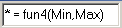 replace the asterisk with the names of the tab and replace Min and Max with the minimum and maximum digital values. For example, if the measurement value should increase proportionally from 26 to 32, the input formula will look as follows:


- Select
 or
 command. The table cells will be filled with calculated data:


- Create a new tab – “H” (
 ) and input the formula of the “F” and “G” tab difference for it


- Select one of the commands for point or section displacement (
 - “Point/ Displace along X”, etc.), open the table in the function window (
 ) and modify the piece by the value in the “H” tab.


Adjusting Pieces According to Measure Table (Using f5)
In order to adjust pieces according to the Measure Table, input the data of the actual measurement of the piece on the screen into one of the “Calculator” tabs; and the Measure Table data into the other. The difference of these two data tables is the piece adjustment value.
An example of the piece adjustment calculation:
- Measure the pieces on the screen to obtain the “Top sleeve circumference” value.
- Display the measurement result for the entire grading (
 ) and save it in the buffer (
 ).


The “F” tab of the “Calculator” will be automatically filled with these data.

- Open the “Calculator” window (
 ) and create a new tab – “G” (
 ).


· Input the Measure Table data for this measurement using the f5 function.
The f5 function allows filling the table quickly when the values are obtained with account for the set increments. To do this:
1) Retrieve the f5 function: click the mouse right button in the expression input box and select  line in the additional pop-up menu
2) In the formula which looks like  replace the asterisks with the names of the tabs and replace Delta with the value of the increment from size to size.
In order to calculate the function right above the open tab input one name of the tab twice.
If the Delta increment is equal to 1cm, the input formula will look as follows:  3) Fill in all values in the basic size line for all heights manually (according to the Measure Table)
4) Select  or
 command. The table cells will be filled with the calculated data:

- Create a new tab – “H” (
 ) and input the formula of the difference of the “F” and “G” tabs


- Select one of the commands of the point or section displacement (
 - “Point/ Displace along X”, etc.), open the table in the function box (
 ) and adjust the shape of the piece by the value in the “H” tab.


|
The f5 function is the only one where the calculation of the function can be performed above the data tab. In other functions a new calculation tab needs to be created.
Determining Increments According to Measure Table (Using f6 and f7)
When piece grading is performed according to the Measure Table data, this increment can be calculated using the f6 (size increment) and f7 (height increment) functions with the previously input data of the Measure Table. Then, these data can be used for piece grading.
- Open the “Calculator” window (
 ) and create a new tab – “G” (
 )
- Input the data of the Measure Table in it (manually or using the f5 function, as described above)


For example, input the data of the half chest circumference measurement:

- Create a new tab – “H” (
 )
- Retrieve the f6 function: in the expression input box click the mouse right button and select
 line in the additional pop-up menu
- In the formula which looks like
 replace the asterisks with the names of the tab of the table where the calculation is performed and the name of the tab whose values the calculation will be performed above (in brackets).


The formula for calculation of the increment in the “H” tab from the “G” tab values looks as follows: 
- Select
 or
 command. The table cells will be filled with the calculated data:


- The total increment value can be distributed for grading. For example, 0.6 proportion of the increment will be applied to the front, 0.4 – to the back. To do this:
1) Create new tabs – “I” and “J” ( )
2) Make formulas of ratios from the “H” tab and input them in the expression box:

3) The result obtained will be saved in the buffer 
4) In the Increment Table ( ) these data can be retrieved from the buffer (
 ) for grading along X or Y

The f7 function of the “Calculator” for calculation of the height increment is used identically to this one.

