Utilities:Global Settings
Contents
Global Settings tab contains Constructor and Design programs settings. This tab is divided into several sub-tabs.
General Tab

-
 - default parameter set in Pieces Parameters window of Constructor program (if no other value was specified for the given Piece Name in Pieces tab of Utilities program).


-
 - default seam size set in Seam Parameters window of Constructor or Design program.


-
 - maximum number of punch pins (for holes punching) on an automatic cutting machine.

-
 - option to block manual entry of Piece Names in Constructor program (Piece Names are entered only in Utilities program).

-
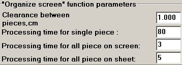 - screen view function parameters:

Arrange Screen and Lay Pieces when drawing
 in Constructor program: spacing between the pieces and speed of their laying out (divide one by time factor).
-
 - possibility of several users creation to work in Constructor program with personal designer’s settings.

No radio button – Constructor program is logged with the settings common for all the designers;
Yes radio button – when logging in, the user’s name and his password are requested. If logged in under your user name, you can enter your personal color and other organization settings. The password protects a model from changes made by another designer.

User Name may be specified in Server program or manually when starting Constructor program.
-
 - displaying the Piece Code box in Piece Parameters window of Constructor program.


-
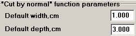 – Normal Line Cut function parameters

-
 – options of a legend on a fold line of symmetrical pieces (FOLD) and on a grainline contour ( haircloth, etc. or none).

The legend characters size is set in Text contour parameters (characters size coefficient is not accounted for).
 - unit of measurement used in Utilities program: centimeters, millimeters, inches.
Notches Tab
Notches size, form and placement settings when drawing pieces from Constructor and Design programs.

 - selection of notches form as viewed in Constructor and Design programs and printed on Designer’s pieces.
Marker and Plotter programs use their own settings of notches form.
 - placement of notches on the symmetry line when
 (Piece/Set Fold Line) function is performed in Constructor program. The Piece Parameters window displays the default settings selected in Utilities program, however these settings may be changed for each individual piece.


Linear Approximation, Grainline, Specification Tab

Linear Approximation Parameters
-
 – accuracy settings for the transition of spline approximation (lines shaping in deformed section).

-
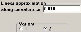 – curved lines shaping settings.

Grainline Parameters
-
 – drawing of arrows on the grainline in Constructor and Design programs.

-
 – grainline deviation unit of measurement set in Marker program.

The factory specifies the deviation units just once, and it is desirable not to change them (or select different deviation unit on pieces as the value of deviation will stay unchanged).
-
 – default parameter used in Piece Parameters windows to set the grainline deviation in Marker program.

There are two options of such deviation setting: % of the grainline length (limit is 100% that is equal to 45 degrees) and degrees (limit is 45 degrees).

-
 – grainline offset from the main contour in
 (Piece/Grainline/From Cut To Cut) function in Constructor program.


This parameter is used when drawing pieces from Constructor program, and in Marker program when unchanged grainline drawing mode is activated (drawn like in Constructor program).
Specification
Piece Specifications and Areas documents may be printed either in Word or Fast Report formats.
The model technical description is displayed only in Fast Report format. To change text in Fast Report format, double click left mouse key anywhere in the text window.
-
 - selection of either Word (checkbox selected) or Fast Report (checkbox empty) format.

To change text in Fast Reportformat, double click left mouse key at any point of the text window. This format utilization allows for the document arrangement change.
-
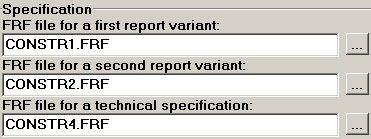 - Specification (1st Report Option), Piece Area (2nd Report Option) and Technical Description windows formation files in Fast Report format.

The form of these documents may be changed. You may use different length and width of cells, enter additional text, etc. and save these changes to be displayed at the next logging in. For this, replace the files with new ones
( program file in Maestro folder).
Plotter, Pieces Tab
The tab contains the default settings entered when drawing the pieces in Constructor and Design programs (Program Settings window, Plotter tab).

-
 - point size to be used when drawing in Design program.

-
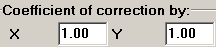 - concordance parameter of drawn up elements and their actual values – default setting of Constructor and Design programs.

Shrinkage coefficient (1.02) or piece mirroring (-1) when drawn on the plotter.
-
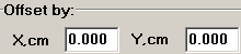 - the value of a piece offset from the paper edge when drawn.

This is a default setting of Constructor and Design programs.
-
 - legend settings for the pieces drawn from Constructor and Design programs (in markers, their own settings are used).

These are default setting of Constructor and Design programs.
-
 - automatic change of the position and size of legend so that it could be fit into the piece Cut contour when pieces are drawn from Constructor and Design programs (in markers, there is a special setting). The Piece Parameters window displays the default mode, however, this setting may be changed for each individual piece.


-
 - a handy pieces operation mode on Constructor program screen: face up or face down. A default parameter set in Piece Parameters window for the whole period of operation. It stays unchanged for different types of overlay in the Marker.

-
 - default setting for the Text contour size (
 Contour/Text) in Constructor program (Settings/Program Parameters, Plotter tab). If a text is applied, the coefficient is set that allows for changing the text characters size (
 - text size as it is set in the Utilities;
 - text is 2 times smaller).


-
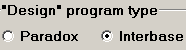 - Design program database version.

