Difference between revisions of "Design:Functions for construction element drafting"
(→Copy line(s)) |
(→Displace lines by superposing line ands) |
||
| Line 1,722: | Line 1,722: | ||
=== Displace lines by superposing line ands === | === Displace lines by superposing line ands === | ||
| − | In order to displace a group of selected (copied) lines, by overlapping its end with the end of the fixed line or curve: | + | In order to displace a group of selected (copied) lines, by overlapping its end with the end of the fixed line or curve: |
* Select or copy lines - (3,4,5) - as described above. | * Select or copy lines - (3,4,5) - as described above. | ||
* Press [[File:Design230.png]] button or execute the "Modifications/ Displace line(s) by overlapping line ends" menu item. The cursor will take the form of [[File:Design231.png]] | * Press [[File:Design230.png]] button or execute the "Modifications/ Displace line(s) by overlapping line ends" menu item. The cursor will take the form of [[File:Design231.png]] | ||
Revision as of 09:19, 20 May 2015
Contents
- 1 Point
- 1.1 Randomly Located Point
- 1.2 Point at Specified Distance and Angle Relative to Another Point
- 1.3 Point Located on Line at Specified Distance
- 1.4 Point Dividing Distance Between Two Other Ones in Specified Ratio
- 1.5 Point Dividing Line (Distance Between Two Points) into N Parts
- 1.6 Rotation of Point Relative to Another Point (by Angle)
- 1.7 Rotation of Point Relative to Another One by Amount
- 1.8 Point Symmetrical to Given Point Relative to Line
- 1.9 Point Located Relative to Another Point on X, Y
- 1.10 Displace Point on X, Y
- 1.11 Point at Specified Distance from Point at Angle to Line
- 1.12 Normal (or Tangent) Point to Point of Line
- 1.13 Normal Line from Point to Line
- 1.14 Point at Distance Specified Along Curve
- 1.15 Displace Point Along Line
- 1.16 Point into Point
- 1.17 Point on Bisector of Angle Between Points
- 1.18 Set Point Vertically (Horizontally)
- 1.19 Point Dividing Line in Specified Ratio
- 1.20 Point(s) Dividing Line(s) into N Parts
- 1.21 Point of Intersection of Vertical and Horizontal Lines
- 1.22 Point of Intersection of Two Lines
- 1.23 Point of Intersection of Line Set by Two Points and Line
- 1.24 Point Located Tangentially to Line
- 1.25 Point of Intersection of Circle with Line
- 1.26 Point of Intersection of Two Circles
- 1.27 Notch
- 1.28 Deleting Point
- 1.29 Renaming Item
- 2 Line
- 2.1 Operations With Straight Lines
- 2.2 Operations With Segments
- 2.3 Operations With Curves
- 2.3.1 Equidistant Line Passing Through Point
- 2.3.2 Equidistant Line
- 2.3.3 Bezier Curve
- 2.3.4 Spline
- 2.3.5 Circle of Specified Radius
- 2.3.6 Arc of Circle Based on Two Points and Center
- 2.3.7 Curve Based on Three Points
- 2.3.8 Explanatory Text
- 2.3.9 Settings and Parameters of Text Input Window
- 2.3.10 Line of Specified Length
- 2.4 Functions
- 3 Modifications
- 3.1 Select line(s)
- 3.2 Copying line (lines)
- 3.3 Displace lines arbitrarily
- 3.4 Move lines along X, Y
- 3.5 Displace lines at normal to another line
- 3.6 Parallel-conic spread
- 3.7 Displace lines to a point
- 3.8 Displace lines by superposing two points
- 3.9 Displace lines by superposing line ands
- 3.10 Displace lines by superposing line ends at extension
- 3.11 Rotating Lines by Angle
- 3.12 Rotate lines by a value, set in length units
- 3.13 Rotate lines arbitrarily
- 3.14 Mirror lines with reference to a line
- 3.15 Mirror lines with reference to X axis
- 3.16 Mirror lines with reference to Y axis
- 3.17 Uniform lines (archiving)
- 4 Constructions
- 5 Measurements (Identifiers)
- 6 Algorithm
The functions of construction drafting are shown in the main and button menus. It is more convenient to access them from the button menu. The functions are joined in individual groups. Each of these groups can be called up by selecting the corresponding tab with the cursor.

If you move the cursor to the button of one of the functions, a prompting message will appear on the screen (the button name, i.e. the information about the function).

If you select the Lines tab, you can obtain a set of buttons for functions related to line construction (as in the example above). When switching to another tab in the menu, the buttons associated with the subject of the specified tab are displayed.

There is a general sequence for setting conditions of execution of functions. Windows for setting conditions for different functions differ, but standard elements for information input are used everywhere:
 - the name of the initial item (a point or line) cannot be changed;
 - the name of the new item (a point or line) can be changed at your own discretion;
If you use the point numbering system provided by the program, the points will be numbered in ascending order. If point names are input manually, you should take care to avoid repetition of denominations.
If a denomination is entered repeatedly, the program will display the following message: The name is not specified or this name already exists. In this case you should return and change the name of the point.
 The new name should consist of alphanumeric characters (including the underscore, if necessary):
First, a letter is entered, then (if necessary) a digit which is followed by an underscore (if necessary), and finally, a letter or a digit. Spaces and hyphens are not used. For example: Т, Т20, Т20_1.
In order to enter an underscore, press  key while holding the SHIFT key down.
 Only the uppercase works when naming elements! Lowercase and uppercase (i.e. “small” and “big” letters) become only “big” ones, in the uppercase: a1 and A1 are perceived as a single name, A1.
Repetition of denominations in the “Initial Data” table and the element name is inadmissible (even if they are entered in different cases).
 - a note for the newly created item can be input if desired. It will be viewed when adjusting the construction algorithm (
 button) in the window bottom line and in the bottom panel of the run screen, in the prompting message field. If a function is performed, a prompting message can be seen in the bottom panel; if you pass through the project execution stages, a comment for the related working stage can be seen in this line, if it has been input.


- The distance can be indicated in digits or using previously entered initial data: select a tab by activating the related switch:

 Then, select the required measure in the data list in the right part of the window
Using
 button send the selected measure to the Distance line. You can perform any arithmetic operations with selected measures or an entered numeric value in this line. Set the cursor after the measure and enter the operational sign from the keyboard and input another measure or a numeric value at the discretion.
An example is shown below.
The values of ratios need to be entered in square brackets to distinguish them from length values.
For example, if you need to enter a half-chest, it will look as follows: Сг/[2] or [0.5]*Сг.

You can see and check the digital value of the entered distance. To do this, press  button. The result will be displayed on the right (as shown in the figure below).

When selecting one of the initial data, its full denomination which has been input by the constructor in the data table is displayed in the status line at the bottom of the window.
- The angle can be specified
 by pressing direction buttons, or you can input it from the keyboard after activation of the cursor in the data input window (by clicking the mouse left button).

You can input identifier names MANUALLY  from the “Initial Data” table (measured angle). These linear values are transferred into angles automatically.
Additional functions: “Stop”, “Back”, “Information”, Selection of Elements
When activating any function in the button menu in the left part of the program window, additional buttons and functions become active:
1.The “Stop”  button allows interrupting execution of the current function;
2.If a number of elements are specified during execution of a function, the “Back”  button allows step-by-step deletion of selected elements (one click on the button is a step back), after which elements need to be specified again. This command operates simultaneously with the main operating function, i.e. you do not have to stop execution of the main function by clicking the mouse right button.
3.The “Information”  button becomes active if incorrect actions have been carried out during the command execution. If you click the button, you can read a message stating the reason why the function is not executed:

There are options for selecting the way of displaying error messages in the 'Program Settings ( button):

The mode described refers to the “Button” type. When working in the “Screen” type, messages are displayed in the center of the run screen at once:

4. Selecting Required Element
If you select an element (a line, a point) on the screen using the cursor and click the mouse left button in the screen bottom area, you can read its name.

If there are several items in this screen area (located close to or on each other), you can select the element required for work.
To do this, press the space bar on the keyboard while holding the mouse left button down. Then, the names of the elements you are indicating at the moment will be written in the screen bottom area. When you see the name of the required item, release the mouse left button.
5. Cancelling operation in the dialog window.
All dialog windows offer the possibility of using the ESC button on the keyboard for cancelling an operation and exiting the dialog window.
Point
In order to work with points, select the Point tab by clicking the left mouse button and then select the necessary command in the horizontal button menu of the tab.
It is important to understand that points in the program are independent working elements, they do not belong to a line, and they can be located on a line or just in the screen area.

Creation of a construction drawing begins with specifying the starting point of reference. It is created in any place of the screen and all further constructions are made relative to it.
Randomly Located Point
In order to set a starting point on the screen, the following operation needs to be carried out:
- Select the Point tab (if it has not been selected yet);
- Select
 button. The cursor of the program will take the form of
 .


Or execute the “Point/ Randomly located” menu item.
- Click the cursor crosshair on any place of the program operational field.
A window for setting the name of the new point will be displayed on the screen:

- Press the “Yes” button to confirm the action or the “Cancel” button to undo.
Attention! The random point will not be reproduced for grading sizes. If a line (any curve) is specified when constructing the point, the point will “lie” on the line and will be located in the same proportion in the grading sizes as in the working size. When the place on the line for plotting the point is indicated, the line will be highlighted in color.
Point at Specified Distance and Angle Relative to Another Point
In order to insert a point relative to another point at a specified distance and angle:
- Select the Point tab (if it has not been selected yet);
- Press
 of the button menu. The cursor will take the form of
 .


Or execute the “Point/ At specified distance” menu item.
- Click with the cursor crosshair on the point relative to which a new one is to be inserted.
- A window for setting parameters of the new point will be displayed on the screen, where you need to enter the distance from the specified point and the angle for constructing the new point.
- Press the “Yes” button to confirm the action or the “Cancel” button to cancel the command execution.

Point Located on Line at Specified Distance
In order to insert a point at a specified distance in the direction of another point:
- Select the “Point” tab (if it has not been selected yet);
- Press
 button of the button menu or execute the “Point/ Between Points at Spec. Dist.” menu item. The cursor of the program will take the form of
 .


- Click with the cursor crosshair on the point (1) from which the distance is to be laid off, then click on the point (2) which determines the direction.
The window for setting parameters of the new point (3) will be displayed on the screen, where you need to input the distance which will be laid off from the first specified point in the direction of the second one.
If a value with the minus sign is input, the distance will be laid off from the first point to the side opposite the direction of the second point.


- Press the “Yes” button to confirm the action or the “Cancel” button to undo.
Point Dividing Distance Between Two Other Ones in Specified Ratio
In order to insert a point dividing the distance between two other points in the specified ratio:
- Select the “Point” tab (if it is has not been selected yet);
- Press
 button of the button menu or execute the “Point/ Dividing dist. between points in ratio” menu item. The cursor will take the form of
 .


- First, click with the cursor crosshair on the point (1) relative to which the dividing ratio is specified, then click on the second point (2).
A window for setting parameters of the new point will be displayed on the screen.


It is where you need to input the ratio by which the distance between the specified points will be divided. The obtained distance will be laid off from the first specified point (1) in the direction of the second specified point (2) and a new point (3) will be inserted.
If the ratio is input with the minus sign, the new point will be placed in the opposite direction from the first one.
- Press the “Yes” button to confirm the action or the “Cancel” button to undo.
Point Dividing Line (Distance Between Two Points) into N Parts
In order to divide a line (or the distance between two points) into the required number of parts:
- Press
 button. The cursor will take the form of
 . Or execute the “Point/ Dividing dist. between two points into N parts” menu item.


- Specify the first point (1) (on the line or just on the screen if the line is not constructed).
- Specify the second point (2) (on the line or on the screen).
The following table will be displayed on the screen:

In the table displayed you should specify the number of parts the line or the distance set by terminal points (if the line is not actually constructed) will be divided into.
The names will be assigned to new points automatically by means of adding indexes to the name of the point recorded manually in the “Point name” window or given by the program in sequence.
Rotation of Point Relative to Another Point (by Angle)
In order to insert a point rotated relative to another point by a specified angle:
- Select the “Point” tab (if it is has not been selected yet);
- Press
 button of the button menu or execute the “Point/ Rotation relative to another point by angle” menu item. The cursor of the program will take the form of
 .


- Click with the cursor crosshair on the point (1) – the center of rotation, then click on the point to be rotated (2).
The window for setting the rotation angle will be displayed on the screen. It is where you need to input the value of the angle (from the keyboard) which the point (2) will be rotated by, and a new point (3) will be inserted in that location. To perform a clockwise rotation, the value is to be positive, for counter clockwise rotation it is to be negative.


- Press the “Yes” button to confirm the action or the “Cancel” button to undo.
Rotation of Point Relative to Another One by Amount
In order to insert a point at the distance laid off in an arc relative to the initial point:
- Select the “Point” tab (if it is has not been selected yet);
- Press
 button. The cursor of the program will take the form of
 . Or execute the “Point/ Rotation relative to another point by amount” menu item.


- Click on the point of the rotation center (1), then on the rotated point (2).


A window for setting the point rotation value will be displayed on the screen where you need to input the distance which will be laid off along an arc from the specified point (2) and a point (3) will be inserted in this location; and select the distance measuring mode: chord wise or along an arc of a circle.
The input value is positive if the rotation is to be clockwise and negative if a counter clockwise rotation needs to be performed.
Press the “Yes” button to confirm the action or the “Cancel” button to undo.
Point Symmetrical to Given Point Relative to Line
In order to insert a point symmetrical to another one relative to a specified line:
- Select the “Point” tab (if it is has not been selected yet);
- Press
 button. The cursor will take the form of
 .


Or execute the “Point/ Symmetrical to given one” menu item.
- Use the cursor crosshair to indicate the initial point (1), then the line (2) which will be the symmetry line.
The window for setting the name of the new point (3) will be displayed on the screen.


- Press the “Yes” button to confirm the action or the “Cancel” button to undo.
Point Located Relative to Another Point on X, Y
In order to insert a point relative to another one by a specified amount on X (Y) axis:
- Select the “Point” tab (if it is has not been selected yet);
- Press
 button. The cursor will take the form of
 .


Or execute the “Point/ Located relative to another one on "X, Y” menu item.
- Click with the cursor crosshair on the point relative to which a new one is to be inserted.
The window for setting the new point coordinates will be displayed on the screen.

Even if one of the coordinate values equals to zero, you still need to fill in both fields: X and Y.
- Press the “Yes” button to confirm the action or the “Cancel” button to undo.
Displace Point on X, Y
In order to displace a point relative to itself by specified coordinates:
- Select the “Point” tab (if it is has not been selected yet);
- Press the button of
 tab. The cursor will take the form of
 .


Or execute the “Point/ Displace on X, Y” menu item.
- Click with the cursor crosshair on the point to be displaced.
A window for setting coordinates of the point displacement will be displayed on the screen:

Even if one of the coordinate values equals to zero, you still need to fill in both fields (X and Y).
- Press the “Yes” button to confirm the action or the “Cancel” button to undo.
Point at Specified Distance from Point at Angle to Line
In order to insert a point relative to another one at a specified distance and angle to a segment or straight line (this function is often used to insert a point perpendicular to a specified line by a specified amount):
- Select the “Point” tab (if it is has not been selected yet);
- Press
 button of the button menu or execute “Point/ At specified distance, at angle to line” menu item. The cursor of the program will take the form of
 .


- Use the cursor crosshair to indicate the point (1) relative to which the new one will be inserted, and then the line (2) relative to which the angle is specified.

- Specify any point (3) on the side from the line where the point is to be laid off.
(This side will be the reference position of the positive direction of angles clockwise from the line).
If there are no points on the selected side, specify a point on the opposite side from the line and input a value with the minus sign.
A window for setting parameters of the new point will be displayed on the screen
It is where you need to enter the distance from the specified point (1) and the angle relative to the specified line (2). A new point (4) will be constructed.
- Press the “Yes” button to confirm the action or the “Cancel” button to undo.
This function does not work with curves (arcs, “Bezier” curves, spline). Besides, the point may not lie on the line at an angle to which a new point will be constructed.
Normal (or Tangent) Point to Point of Line
In order to put a point on the normal (or tangent) line from a given point on a line (a straight line, segment or curve):
- Press
 button. The cursor will take the form of
 . Or execute the “Point/ Normal (tangent) to point of line” menu item.


- Specify the point (1) on the line, then specify the line (2) where this point is located.
- Specify the point (3) which determines the positive direction (any point on the screen on the side from the line where the normal or tangent line is to be constructed).
The following table will be displayed on the screen:

If there are no points on the selected side, you need to select a point on the opposite side and input a value with the minus sign.
In the table the distance is set which the point (4) is to be inserted at normally (or tangentially) from the point (1) on the line (2). The distance is set arbitrarily or using initial data.


FIG.1 FIG.2
Whether the point will be constructed normally or tangentially to the line depends on the state of the switch in the “Direction” field: Normal (fig. 1) or Tangent (fig. 2)
Construction of a point normally to a line (fig. 1) is used, for example, when drafting a sleeve cap or constructing a side line. When the point (4) is constructed normally from the point (1) on the line (2) at some distance, a curve (spline) is then formed based on these points.
Setting of a point tangentially to the line (fig. 2) can be used when constructing collars.
For example, you need to construct a point (4) located on a tangent line to the neck line (2) of the front from the shoulder highest point (1) at the distance equal to the size of the back neck (preliminarily measured and input as an identifier)
 The point selected for drafting a normal (or tangent) line from it can be located in the middle of a line or be a terminal point (at the joint of two homogeneous or heterogeneous lines) but it must be located on a line.
Normal Line from Point to Line
In order to create a point lying on the normal line drawn from a specified point, on a line:
- Select the “Point” tab (if it is has not been selected yet);
- Press
 button of the button menu. The cursor will take the form of
 . Or execute the “Point/ Normal line from point to line” menu item.

- Set the cursor crosshair at the point (1) which the normal line will be drawn from and click the mouse left button;
- Set the cursor crosshair on a line of any type (2) where the point will be constructed and click the mouse left button;
- A command dialog window will be displayed on the screen where you can enter the point name manually or add a comment, if necessary:

- Press the “Yes” button to confirm the action or the “Cancel” button to undo.


The point (3) is constructed at the minimum distance from the point (1), i.e. on the normal line from the point.
Point at Distance Specified Along Curve
In order to insert a point relative to another point at a distance specified along a curve:
- Select the “Point” tab (if it is has not been selected yet);
- Press
 button of the button menu. The cursor will take the form of
 .


Or execute “Point/ At distance specified along curve” menu item.
- Use the cursor crosshair to indicate the terminal point (1) of the line relative to which a new one is to be inserted, then the line (2) along which the distance needs to be set.
Enter the distance from the specified point (1) in the parameter setting window for the new point (3)

If a negative value is input, the point created will not be located on the line; it will be on a tangent line to the line in the specified terminal point.

Option 2: If a point located in the middle of the line is specified instead of the line terminal points, the command will be executed in a slightly different way (fig. 2):
- Specify the point (1) on the line from which the new point will be inserted at the specified distance
- Specify the curve (2) where the point is located
- Specify the point (3) on the line which determines the positive direction (one of the terminal points of this curve)
Input the distance from the selected point (1) to the newly constructed point (4) in the parameter setting window which is displayed on the screen. If you input a value with the minus sign, the distance will be laid off the opposite way from the point determining the direction.

- Press the “Yes” button to confirm the action or the “Cancel” button to undo.
This function does not work with infinite straight lines.
Displace Point Along Line
In order to displace a point along the line it lies on:
- Select the “Point” tab (if it is has not been selected yet);
- Press
 button of the button menu. The cursor will take the form of
 . Or execute the “Point/ Displace point along line” menu item.


- Specify the point to be displaced (1), then the line (2) the point lies on, and then any point (3) on this line determining the positive direction of displacement;
- A command dialog window will be displayed on the screen where you need to input the amount of displacement manually or using “Initial Data”:


- If you enter a value with the minus sign, the distance will be laid off the opposite way from the specified direction.
- Press the “Yes” button to confirm the action or the “Cancel” button to undo.
The function works with any types of lines except infinite straight lines, and it does not work with terminal points of lines.
Point into Point
In order to displace a point in the drawing to a specified point:
- Select the “Point” tab (if it is has not been selected yet);
- Press
 button of the button menu. The cursor will take the form of
 . Or execute the “Point/ Point into point” menu item.


- Specify the fixed point (1), then the point to be displaced (2).

The point (2) is displaced so that the drawing elements passing through this point will also be displaced or deformed.
This is with the exception of the points located on segments (if these points are not terminal ones) and infinite straight lines. The points will be displaced but the lines will not be deformed.
Point on Bisector of Angle Between Points
In order to set a point at a specified distance on bisector of an angle between points:
- Press
 button of the button menu. The cursor will take the form of
 .


Or execute the “Point/ On bisector of angle between points” menu item.
- Specify the point (1) at the set distance from which the new point will be located.
- Specify the first point (2) and the second point (3) determining the angle.
A window for setting parameters for the new point will be displayed on the screen (4):


- Enter the offset value for the newly created point (4) from the point (1) along the bisector using some initial data or input the distance manually.
If a value with the minus sign is input, the new point will be inserted on the opposite side on the bisector of the angle between the points (2) and (3). The order in which the points (2) and (3) determining the angle for the bisector are set does not matter, but the point will always be created for the acute angle between the specified points.
- Press the “Yes” button to confirm the action or the “Cancel” button to undo.
Set Point Vertically (Horizontally)
In order to set a point vertically relative to a given point:
- Press
 button of the button menu. The cursor will take the form of
 . Or execute the “Point/ Set vertically (horizontally)” menu item.


- Specify the fixed point (1) relative to which the displaced point will be located vertically;
- Specify the point to be displaced (2).

In order to set a point horizontally relative to a given point, take the same actions but after selecting the command button press the CTRL key on the keyboard (to switch to the second mode of this function operation).
In this case, the point (2) will be displaced to the vertical (or horizontal) line drawn from the fixed point (1)
Point Dividing Line in Specified Ratio
In order to divide a line or a curve in a specified ratio:
- Press
 button of the button menu. The cursor will take the form of
 . Or execute “Point/ Dividing line in specified ratio” menu item.


- Use the cursor to indicate a line (or a curve) (1) close to the terminal point (3) or (4) from which a new point (2) will be set in the specified ratio.
- A table will be displayed where the proportion (ratio) is to be set.


- After setting the ratio, press the “Yes” button or “Cancel” to cancel the selection.
Point(s) Dividing Line(s) into N Parts
In order to divide a line (curve) into a specified number of parts:
- Press
 button or execute the “Point/ Dividing line(s) into N parts” menu item. The cursor will take the form of
 .


- Specify the line (1) which is to be divided into N parts.
A parameter setting window will be displayed on the screen:

Specify the number of parts the section or the group of sections is to be divided into in the table.

Names will be automatically assigned to new points by means of adding indexes to the point name input manually in the “POINT NAME” window or to that provided by the program in sequence.
- After the number of parts has been set, press the “Yes” button to confirm or “Cancel” to cancel the selection.
- Press
 button or execute the “Point/ Dividing line(s) into N parts” menu item. The cursor will take the form of
 .


A prompting message will be displayed at the bottom corner of the screen 
- While holding the SHIFT key on the keyboard down, move the cursor and click the mouse left button on several selected lines (1),(2),(3) successively and release the SHIFT key when the selection is finished.
A parameter setting window will be displayed on the screen (see above)

Names will be automatically assigned to new points by means of adding indexes to the point name input manually in the “POINT NAME” window or to that provided by the program in sequence
- After the number of parts has been set, press the “Yes” button to confirm or “Cancel” to cancel the selection.
When working with the SHIFT key you can specify lines of different statuses (segments, splines, Bezier curves, arcs)
In order to obtain an accurate result when working with several lines, you should make sure that the end of the first line is the beginning of the second one, etc. It means that accurate mating of lines is required (if necessary, you can use the function of dividing a line at a point (  function in the Lines tab described below)).
Point of Intersection of Vertical and Horizontal Lines
In order to find the point of intersection of a vertical line from one point and a horizontal line from another one:
- Select the “Point” tab (if it is has not been selected yet);
- Press
 button of the button menu. The cursor will take the form of
 . Or execute “Point/ Intersection of vertical and horizontal lines” menu item.


- Use the cursor crosshair to indicate the point (1) which the vertical line is to be drawn down from; then the second point (2) which the horizontal line is to be drawn from.
A window for setting parameters of the new point (3) will be displayed on the screen.


Execution of this command does not require vertical and horizontal lines that are actually constructed. Imaginary vertical and horizontal lines are drawn from the specified points.
- Press the “Yes” button to confirm the action or the “Cancel” button to undo.
Point of Intersection of Two Lines
In order to insert a point at the intersection of any two lines:
- Select the “Point” tab (if it is has not been selected yet);
- Press
 button of the button menu. The cursor will take the form of
 .


Or execute the “Point/ Line intersection” menu item.
- Use the cursor crosshair to indicate one of the lines (1), then the second one (2).
A window for setting parameters of the new point (3) will be displayed on the screen.
- Press the “Yes” button to confirm the action or the “Cancel” button to undo.
When this command is executed, all possible points of intersection of the two lines are found. Intersection may not be an explicit one, but can be on the extension of the selected lines. If lines intersect at several points, each of them will be given a special name (e.g. Р20 and Р20_1)
Point of Intersection of Line Set by Two Points and Line
In order to find the point of intersection of a segment (set by two points or actually constructed) with a section:
- Press button. The cursor will take the form of . Or execute the “Point/ Intersection of line set by two points and line” menu item.
- Specify the first point (1) determining the segment.
- Specify the second point (2), determining the segment.
- Indicate the line (segment or curve) (3) which the segment set by two points (1-2) is to intersect.
A table for setting the name for the new point (4) will be displayed on the screen:


The name of the point can be changed or a comment can be added in the table, if necessary.
- After the name of the point has been set and a comment has been recorded (if necessary), press the “Yes” button to confirm or the “Cancel” button to cancel the selection.
Point of Intersection of Two Lines Set by Two Points
In order to find the point of intersection between two straight lines specified by two points:
- Press
 button. The cursor will take the form of
 . Or execute the “Point/ Intersections of lines set by two points” menu item.


- Specify the first point (1) determining the first line.
- Specify the second point (2) determining the first line.
- Specify the first point (3) determining the second line.
- Specify the second point (4) determining the second line.
A window for setting parameters of the new point (5) will be displayed on the screen.


The point name can be changed and a comment can be added in the table, if desired
- After the name of the point has been set and a comment has been recorded (if necessary), press the “Yes” button to confirm or the “Cancel” button to cancel the selection.
Point Located Tangentially to Line
In order to insert a point at the intersection of a tangent line with a line:
- Select the “Point” tab (if it is has not been selected yet);
- Press button of the button menu or execute the “Point/ On tangent line to given line” menu item. The cursor will take the form of .
- Specify the point (1) which the tangent line is to be constructed from, then the curve (2) which the tangent line is to be constructed to (specify the line from the side of the projected point)
- A window for setting parameters of the new point (3) will be displayed.
- Press the “Yes” button to confirm the action or the “Cancel” button to undo.
Point of Intersection of Circle with Line
In order to insert a point at the intersection of a circle with a line:
- Select the “Point” tab (if it is has not been selected yet);
- Press
 button of the button menu. The cursor will take the form of
 .Or execute the “Point/ Intersections of circle with line” menu item.


- Specify the point the point of the circle center (1), then, the intersection line (2), and then one of 2 possible points (3) of the circle intersection with the line nearest to the intersection (a circle can intersect a line at two points).
A parameter setting window will be displayed on the screen where you need to input the circle radius:


An actually constructed circle is not required for execution of this command.
- Press the “Yes” button to confirm the action or the “Cancel” button to undo.
Point of Intersection of Two Circles
In order to insert a point of intersection of two circles:
- Select the “Point” tab (if it is has not been selected yet);
- Press
 button of the button menu. The cursor will take the form of
 .


Or execute the “Point/ Intersection of Two Circles” menu item.
- Specify the point of the first circle center (1), then the center of the second circle (2), and then the point (3), nearest to the place of intersection (two circles can have two intersection points).
A window for setting parameters of the new point (4) will be displayed on the screen.


It is where you need to input the values of the first and second circle radius
Actually constructed circles are not required for execution of this command.
- Press the “Yes” button to confirm the action or the “Cancel” button to undo.
Notch
In order to create a notch:
- Select the “Point” tab (if it is has not been selected yet);
- Press
 button of the button menu. The cursor will take the form of
 .


Or execute the “Point/ Set (delete) notch” menu item.
- Specify a point previously constructed by one of the construction functions on the screen.
When working in the Drawing window a triangle will be constructed in the position of the point, and when working in the “Piece Handling” window a notch will be set.

- In order to delete a notch, take the same actions. One more click on the point with the notch will delete it replacing it with a point.
A notch cannot be created independently without previous creation of a point.
 A notch will appear on the assembled outline and piece (in the “Piece handling” mode) only if the stage of its creation will be at least one level higher than the stage of creation of lines through this notch (or just after creation of the point).
This can be achieved using “Move operator up”  or “Insert operator before current one”
 commands in the “Program debugging” window.
It means that if you create a curve based on points and then replace the points with notches, this line will not have notches in pieces!
Deleting Point
In order to delete any point in the project:
- Press
 button. The cursor will take the form of
 . Or execute the “Point/ Delete point” menu item.

- Specify the point (or a few points successively) to be deleted on the drawing.
This deletion of points will not destroy the project. This command enables getting rid of unnecessary points overloading the project.
 If an infinite line has been drawn from a point, this line will also be automatically deleted when deleting the point.
Renaming Item
In order to rename an item in the drawing (a point, line or outline) indicated on the screen:
- Select the “Point” tab (if it is has not been selected yet)
- Press
 tab button. The cursor will take the form of
 .


Or execute the “Project/ Rename item” menu item.
- Indicate the drawing element to be renamed on the screen.
- The window will be displayed on the screen where the new name of the item needs to be input:

- Press the “Yes” button to confirm the action or the “Cancel” button to undo.
This stage of work will be recorded in the algorithm and further in the text the renamed elements will be recorded with new names.

ATTENTION: This function is not intended for execution using the “Insert operator before/ after current one” function  in the Program Debugging window. In this case, the function will be executed, but the names will not be changed in the further text of the algorithm.
This function differs significantly from the similar command in the Program Debugging window where renaming is performed in the algorithm editing mode. An element is renamed automatically throughout the entire text of the algorithm where it is mentioned, and this renaming stage is not recorded in the algorithm.

Line
The following types of lines are offered by the program for drawing:
- Straight lines
- Splines
- Arcs of circles
- Circles
- Segments
In order to construct and handle lines, go to the Lines tab of the upper button menu:

Operations With Straight Lines
Straight Line from Point at Random Angle
In order to construct a straight line from a point at a certain angle (throughout the entire screen):
- Select the “Line” tab (if it is has not been selected yet);
- Press
 button of the button menu. The cursor will take the form of
 .


Or execute “Lines/ Straight line from point at angle” menu item.
- Specify the point (1) which the straight line is to be constructed from.
A window for setting parameters of the straight line (2) will be displayed on the screen.
It is where you need to input the value of the angle (clockwise) at which the straight line will pass, either inputting the angle value manually or using the arrows around the angle value setting box.


- Press the “Yes” button to confirm the action or the “Cancel” button to undo.
ATTENTION: When a point which an infinite straight line is drawn from, is displaced, this straight line will also be displaced because it cannot exist without its initial point on the screen.
Straight Line from Point at Angle to Given Line
In order to construct a straight line from a point at a certain angle to a specified line:
- Select the “Line” tab (if it is has not been selected yet);
- Press
 button of the button menu. The cursor will take the form of
 .


Or execute the “Lines/ Straight line from point at angle to line” menu item.
- Specify the point (1) the straight line will be constructed from, then the line (2) relative to which the angle will be determined (clockwise).
A window for setting parameters of the new straight line (3) will be displayed on the screen where you need to input the value of the angle which the straight line will be constructed at relative to the specified line.
- Press the “Yes” button to confirm the action or the “Cancel” button to undo


Bisector of Angle Between Two Lines
In order to construct a straight line from a point which is the bisector of the angle formed by straight lines, curves or segments:
- Select the “Line” tab (if it is has not been selected yet);
- Press
 button of the button menu. The cursor of the program will take the form of
 .


Or execute the “Lines/ Bisector of angle between lines” menu item.
- Specify the point of the angle center, then one of the angle sides and then the other angle side. The angle sides must be straight lines or segments.
A window for setting parameters of the new straight line will be displayed on the screen.

- Press the “Yes” button to confirm the action or the “Cancel” button to undo.
As a result of the function execution, the program offers two straight lines: all variants of bisectors, because four angle types can be formed of two straight lines


The function also works with curves (arcs, splines) upon condition of their accurate mating in the bisector initial point. It passes tangentially to these lines at this point of the joint.
Straight Line Parallel to Given Line
In order to draw a line parallel to the specified straight line or section (the function does not work with curved lines):
- Select the “Line” tab (if it is has not been selected yet);
- Press
 button of the button menu. The cursor will take the form of
 .


Or execute the “Lines/ Straight line parallel to line” menu item.
- Specify the line (1) parallel to which the straight line will be constructed.
- Specify a point (2) on any side from the line. This direction will be considered positive for setting the value of the parallel line.
A window for setting parameters of the new straight line (3) will be displayed on the screen.


It is where you need to input the distance from the specified line (1) for the new straight line (3) to be constructed at.
If you set a value with the negative sign, the parallel straight line will be constructed on the other side. Therefore, if there are no points on the side selected (as the positive one), you need to specify a point on the opposite side and enter a value with the minus sign.
- Press the “Yes” button to confirm the action or the “Cancel” button to undo.
Operations With Segments
Segment Between Two Points
In order to construct a segment between two points:
- Select the “Line” tab (if it is has not been selected yet);
- Press
 button of the button menu. The cursor of the program will take the form of
 .


Or execute the “Lines/ Segment between points” menu item.
- Specify the first point (1) and the second point (2) which need to be connected with a segment.
The window for setting parameters of the new segment (3) will be displayed on the screen.


- Press the “Yes” button to confirm the action or the “Cancel” button to undo.
Segment from Point to Point of Intersection with Straight Line (Segment)
In order to draw a segment from a point to the point of intersection with a straight line (segment) at an angle:
- Select the “Line” tab (if it is has not been selected yet);
- Press
 button of the button menu. The cursor of the program will take the form of
 .


Or execute the “Lines/ Segment from point at angle to line” menu item.
- Specify the point (1), then the section (straight line) (2) whose intersection at the specified angle needs to be found. The window for setting parameters of the new section (3) will be displayed on the screen where you need to input the angle the intersection is to be found at.


- Press the “Yes” button to confirm the action or the “Cancel” button to undo.
A segment of the intersection to the curve (arc, spline, etc.) is not created
Segment of Specified Length
In order to construct a segment of a specified length at a specified angle:
- Select the “Line” tab (if it is has not been selected yet);
- Press
 button of the button menu. The cursor of the program will take the form of
 .


Or execute the “Lines/ Segment of specified length” menu item.
- Specify the point (1) relative to which the segment is to be constructed.
A window for setting parameters of the new section (2) will be displayed on the screen


Input the length of the segment (2) and the angle (clockwise) the segment is to be constructed at.
- Press the “Yes” button to confirm the action or the “Cancel” button to undo.
Vertical (Horizontal) Line from Point to Intersection with Line
In order to draw a vertical segment from a point to the intersection with a line:
- Press
 button of the button menu. The cursor will take the form of
 . Or execute the “Lines/ Vertical (Horizontal) line to line” menu item.


- Specify the point (1) which the vertical segment will be drawn from;
- Specify a line of any type (2) limiting the segment.
A parameter setting window will be displayed on the screen where the name of the segment or that of its second terminal point (3) can be changed or a comment can be added, if desired:


- Press the “Yes” button to confirm the action or the “Cancel” button to undo.
This will result in constructing a vertical segment (1-3) from the point (1) to the line (2). (See Fig.1)
In order to draw a horizontal segment from a point to the intersection with a line, take the same actions but after selection of the command button, press the CTRL key on the keyboard (to switch to the second operational mode of this function).
This will result in constructing a horizontal segment (1-3) from the point (1) to the line (2). (See Fig.2)
If there is no explicit intersection between the initial line and the created segment, the segment will be drawn to the intersection with the extension of the limiting line (on the tangent line from the terminal point).
Operations With Curves
Equidistant Line Passing Through Point
In order to draw an equidistant line from a point from a given line (segment or curve):
- Press
 button of the button menu. The cursor will take the form of
 .


Or execute the “Lines/ Equidistant line passing through point” menu item.
- Specify the point (1) which the equidistant line will be drawn from;
- Specify the line (2) the parallel should be constructed from.
- A parameter setting table will be displayed on the screen where the equidistant line name can be changed or a comment can be added, if desired:


- After you have set the equidistant line name and added a comment (if necessary), press the “Yes” button to confirm the action or the “Cancel” button to cancel the selection.
NOTE: The point (1) of the equidistant line drawing does not actually lie on the created line. It is only used for measuring the distance to the initial line (2). Therefore, if this point has the “Notch” status, this notch will not be present on the created equidistant line in the ready piece.
Equidistant Line
In order to construct a line parallel to a given line (a segment or curve), and drawn for the amount of the specified offset:
- Press
 button of the button menu. The cursor will take the form of
 .


Or execute the “Lines/ Equidistant line” menu item.
- Specify the start of the line (1) close to the terminal point
- Specify the end of the line (2) close to the terminal point
A table for setting parameters of the offset from the selected line will be displayed on the screen:


Table handling options:
Option 1: set a constant value of the equidistant line offset (i.e. a parallel line from the line) by inputting an arbitrary value (in units of length) in the “At the start” field or using initial data.
When specifying the start and the end of the line, we determine the direction of movement. On the right in the direction of movement (from 1 to 2) an equidistant line will be constructed.
If a value with the minus sign is set, the equidistant line will be constructed on the opposite side from the line.
Option 2: set a variable value of the equidistant line offset from the line, i.e. different values for the start and the end of the line.
To do this:
1) in the “At the end” field activate the operating mode switch:


2) Set the value of the offset from the section start in the “At the start” field (in units of length or using initial data).
3) Set the value of the offset from the section end in the “At the end” field (in units of length or using initial data).
In this case the equidistant line width will be variable. The equidistant line name can be changed or a comment can be added in the table, if desired.
- After you have set the equidistant line name and added a comment (if necessary), press the “Yes” button to confirm the action or the “Cancel” button to cancel the selection.
Note: The “Equidistant lines” created will have the status and properties of a “Spline”.
Bezier Curve
In order to construct a Bezier curve based on two points:
- Select the “Line” tab (if it is has not been selected yet);
- Press
 button of the button menu. The cursor will take the form of
 . Or execute the “Lines/ Bezier curve” menu item.


- Use the cursor crosshair to click on the points (1) and (2) successively which will be used to construct the Bezier curve. A section in the form of a line with two supplementary segments (“arms”) will appear on the screen between the two points. (See Fig.1)
- Without releasing the mouse left button, successively rotate and freely move the points (3) and (4) at the ends of the “arms”. Thus, you can set the angle and the bend of the line.
- Deformation takes place until the mouse left button is released. Then you can set the cursor crosshair at the end of the pivot (3) or (4) again – (See Fig.2)
- After the shape of the line is specified, you should deactivate the function by pressing the mouse right button. The new shape of the line will be fixed. – (See Fig. 3)

Fig.1 Fig.2 Fig.3
A window for setting the curve parameters will be displayed on the screen:

- Press the “Yes” button to confirm the action or the “Cancel” button to undo.
Spline
In order to construct a spline (curve) based on certain points:
- Select the “Line” tab (if it is has not been selected yet);
- Press
 tab button. The cursor will take the form of
 .


Or execute the “Lines/ Spline” menu item.
- Specify successively the points (1,2,3,4,5,…) for the spline line drawing. (See Fig. 1)
- Click the mouse right button to complete the spline construction. (See Fig. 2)

A window for setting parameters of the spline will be displayed on the screen:

- Press the “Yes” button to confirm the action or the “Cancel” button to undo.
Circle of Specified Radius
In order to construct a circle of a specified radius with the center in a specified point:
- Select the “Line” tab (if it is has not been selected yet);
- Press
 tab button. The cursor will take the form of
 .


Or execute the “Lines/ Circle” menu item.
- Specify the point (1) which will be the center of the circle. A window for setting the circle parameters will be displayed on the screen and the radius is to be input there.
- Press the “Yes” button to confirm the action or the “Cancel” button to undo.
The circle created has one point – the place of the joint of the line “start and end”.


Arc of Circle Based on Two Points and Center
In order to construct an arc of a circle based on two points and the center:
- Select the “Line” tab (if it is has not been selected yet);
- Press
 tab button. The cursor will take the form of
 .


Or execute the “Lines/ Arc of circle based on two points and center” menu item.
- Specify the point of the circle center (1), then the first point limiting the arc and determining the radius of the circle (2), and then the second point limiting the arc (3) setting the level of the arc drawing end level (5) to the point (4)
A window for setting parameters of the arc will be displayed on the screen:

- Press the “Yes” button to confirm the action or the “Cancel” button to undo.
Arc of Circle Based on Three Points

In order to construct an arc of a circle based on three points:
- Select the “Line” tab (if it is has not been selected yet);
- Press
 tab button or execute the “Lines/ Arc of circle based on three points”. The cursor will take the form of
 .


- Specify the first point limiting the arc (1), then an intermediate point of the arc (2) and then the last point limiting the arc (3).
A window for setting parameters of the arc will be displayed.


- Press the “Yes” button to confirm the action or the “Cancel” button to undo.
Curve Based on Three Points
In order to construct a curve of the parabolic type based on three points:
- Select the “Line” tab (if it is has not been selected yet);
- Press
 tab button. The cursor will take the form of
 . Or execute the “Lines/ Arc of circle based on three points” menu item.


- Specify the first limiting point of the curve (1), then the external point of the curve (2) and then the last limiting point of the curve (3).
A window for setting parameters of the curve will be displayed.


Press the “Yes” button to confirm the action or the “Cancel” button to undo.
Arbitrary Line
In order to construct an arbitrary line:
- Select the “Line” tab (if it is has not been selected yet);
- Press
 button of the button menu. The cursor of the program will take the form of
 . Or execute the “Line/ Arbitrary line” menu item.


- Use the cursor crosshair to indicate either the point (1), or the line (2) (it will be highlighted in color) or a random place on the screen (3).
- After all necessary drawing elements the arbitrary line is to pass through have been indicated, click the mouse right button;
- A command dialog window will be displayed on the screen where you can record the line name manually or add a comment, if necessary:


- Press the “Yes” button to confirm the action or the “Cancel” button to undo.
- A line which in fact has the status of a “Spline”, will be drawn through the specified points. It will be constructed based on the principle of the “Rigid Ruler” at the bend points, as well as the spline.
ATTENTION: when a line is created through a random place on the screen, this point will not be reproduced in sizes (when working with the Size Base)! If the arbitrary line is drawn based on points of the drawing, reproduction of these points will also be assigned to points of the created line.
Explanatory Text
If some textual denominations displayed on guiding straight lines from certain points of the drawing need to be introduced to the project:
- Select the “Line” tab (if it is has not been selected yet);
- Press
 button of the button menu or execute the “Lines. Explanatory text” menu item. The cursor of the program will take the form of
 .


- Specify the points (1) and (2) successively, which the straight line construction will be based on.
- A straight line will be constructed on the screen between the specified points with arrows directed to the selected points. Positioning of this straight line on the screen needs to be selected:

If the inscription line needs to be removed from the straight line between the points, perform displacement of the straight line in accordance with the prompting messages of the screen bottom panel right after selection of the points (1) and (2):
- First, you can use the “Up”
 and “Down”
 keys to provide displacement up or down from horizontal (or those close to horizontal) lines and to the right or to the left from vertical (or those close the vertical) lines respectively;


- Using the “Left”
 and “Right”
 keys, you can displace the points of arrow ends along the removed straight line inward or outward. If an offset from the straight line between the points has not been performed first (as described above), this displacement makes no sense.


Use the keys with digits “1”, “2”, “3” to select the type of the straight line direction between points: 1 –in the direction between the points, 2 – horizontally, 3 – vertically.

- Click the mouse right button. A window for setting parameters will be displayed on the screen to type a text or add a comment, if necessary.

- Input the text in the “Text” field.
- Press the “Yes” button to confirm the action or the “Cancel” button to stop the command operation.
Settings and Parameters of Text Input Window
1). Any symbols can be used, although the following symbols will be ignored: “?”, “№”, “”, “,”. The “Period” and “Semicolon” symbols will be recorded as “@” and “~” in the algorithm text while they will look normally on the screen. In order to create a word space, use the underscore “_”.


2). “Name”: You should either record the required name of the line manually in the cell, or select automatic naming of lines in sequence  .
3). “Color”: Input the numbers of colors from the “Program setting” window (  button) in the “Color Palette ” tab into the color selection cell
 to select the color which will be used to inscribe the Text. You should input the sequential number of the color, not the number above the cell with the required color (-10, -9,…).

4). “Size”: Input the ratio for the previously specified size of the text into  cell in the “Program setting” window (
 button) of the “Graph Plotter” tab.

For example, if the ratio is 0.5, the size of letters will be half the size currently set in the setting window.
5). “Arrows”:  setting allows either avoiding displaying arrows at the ends of the straight line created for the text (uncheck the checkboxes by clicking the mouse left button:
 ), or displaying arrows at both ends (both boxes are checked), or only at the start or at the end respectively (in the order of clicks when creating the line).
6). “Orientation”: This setting allows orientating the text itself relative to its position along the created line:

When the switch is set in one of the 4 modes, the text will be either written along the line from its point 1 to point 2 (“Normal”); or from point 2 to point 1 (“Reverse”); or horizontally or vertically, not along the line (“Horizontal”, “Vertical”).

7). “Positioning”:  setting specifies the location of the text relative to its guiding line. When the required switch is set by the mouse left button click, in the “At the start” and “At the end” modes the initial point of the text will be referred to the 1st or 2nd point of the line creation respectively. In the “In the center” mode the text will be located in the middle of the line.

Note: If the text which has already been created or its parameters need to be edited, you can either create a new text, or select the mode of the right menu of the “Program debugging” function (  button) – “Operator editing”.
a) Click the mouse right button on the “Text” operator line and select the “Edit operator” function in the pop-up menu.

b) You can change parameters of the “Program text” field in the “Operator editing” window:

c) The parameters in the parentheses can be changed manually in this field. For example, for (L80, P62, P63, Шп+Пшп, 0, 0.01, 0, 1, 1, 3, 1, 1) line, parameters mean respectively: L80 – the name of the text guiding line (it is recommended to not change this);
P62, P63 – the names of the points which were used to create the line for the text;
Шп+Пшп – the text (when changing it here, you can also correct it in the “User’s text” field below, although it is just formal record for the text in the algorithm window);
The first three digits after the text ( 0, 0.01, 0) are the settings of the text line position relative to the setting points (described above):
The first digit (0) signifies the type of the straight line direction between points (select using the following keys on the keyboard: “1” (in the direction between points), “2” (horizontally), “3” (vertically). Here, 0 is for type “1”, 1 is for type “2” and 2 is for type “3” respectively.
The second digit (0.01) is the bevel of the line to the specified offset.
The third digit (0) is the value of the offset from the line set based on the points
The fourth digit (1) is the “Text color” setting. You can replace the digit with another value from the color setting parameters.
The fifth digit (1) is the “Text size” setting. You can replace the set ratio of the previously set text parameters in the program settings.
The sixth digit (3) is the setting for “Arrow displaying” on the text line:
0 – arrows are not to be drawn; 1 – to be drawn at the start only; 2 – to be drawn at the end only; 3 – to be drawn on both sides
The seventh digit (1) – “Inscription orientation” setting:
1 –Normal; 2 –Reverse; 3 –Horizontal; 4 –Vertical
The eighth digit (1) – “Inscription positioning on the line”:
1 – in the center; 2 – at the start of the line; 3 – at the end of the line
- The visibility of the input text can be removed from the screen in the drawing element visibility block using the “Display text” button.

In order to set the required parameters of the input text:
- Select the “Program settings” menu button
 . A setting window will be displayed on the screen.

- Select the “Graph plotter” tab
- Select the “Text” Outline setting and input the required dimensions of characters (letters, digits) in the “Size” field and spaces between them in the “Spacing” field. The parameters must be input in the measurement units set for the entire work in the project. Press the “Yes” button for temporary application (until the program reset).
- For permanent application, the setting is to be recorded by pressing the “Save” button.
- If the selected settings are not to be applied, press the “Cancel” button.
Line of Specified Length
In order to construct a curve of a specified length based on two points:
- Select the “Line” tab (if it is has not been selected yet);
- Press
 button of the button menu. The cursor will take the form of
 .


Or execute the “Lines/ Line of specified length” menu item.
- Specify successively the points (1) and (2) the curve will be constructed between and the direction setting point (5) on one of the sides relative to the imaginary straight line drawn between the two selected points.
- A window for setting the length of the curve to be created will be displayed on the screen. Input the required value in the “Length” field, either manually or using the data of the “Initial data” table tabs:

- Press the “Yes” button to confirm the input parameters. An arc of the specified length will appear on the screen between the two points (1 and 2) which will be bowed in the direction of the guiding point (5) as a curve with 2 supplementary segments – “arms” (See Fig. 1)
- While holding the mouse left button down, rotate and move the points (3) and (4) at the ends of the “arms” freely. This is how you can specify the angle and the bend of the line.
- Deformation takes place until the mouse left button is released. Then, you can set the cursor crosshair at the end of the pivot (3) or (4) again – (See Fig.2)
- After the shape of the line has been specified, the function needs to be deactivated by pressing the mouse right button. The new shape of the line will be fixed. – (See Fig. 3)

Fig.1 Fig.2 Fig.3
For example, this function can be used when constructing sections of the sleeve cap of a specified length (equal to the length of the corresponding section of the scye multiplied by the fit coefficient) in order to create a sleeve with the desired fit value.
Functions
Deforming Line Arbitrarily
In order to deform a line arbitrarily:
- Select the “Line” tab (if it is has not been selected yet)
- Press
 button of the button menu. The cursor will take the form of
 . Or execute the “Lines/ Deform arbitrarily” menu item.


- Specify the point (1) which belongs to the line to be deformed (3)
- While holding the mouse left button down, move the cursor freely to the required position on the screen. You can see the initial position of the line on the screen at the same time.
- When the desired deformation has been achieved, click the mouse right button. The point (1) will then move to its new position (2).
Note: Deformation of segments and straight lines is not performed. But segments can be deformed by means of terminal point moving.


When clicking on the point (1) the coordinates of the cursor will be shown at the bottom right corner of the screen (here, they coincide with the point (1)) set to zero.
As the point is moved, the values of the projection onto the X-axis (Dx first box), onto the Y-axis (Dy second box) and the straight-line distance to the point of origin (the third box) will be changed:

It means that the value of the performed deformation (the amount of the point displacement) can be seen.
Deformation Option:
You can specify deformation for a line if there are no points on it (Fig. 2)
In this case, you should specify the line itself (1), instead of a point on the line, when executing the command. Further actions are the same as described above.

In this case, the points (2) and (3) on this line will be the borders of the area to be deformed – they will not be moved during the line deformation.
Deformation Option:
If you specify a terminal point for deformation where a few various lines (segments, curves) converge, the deformation will be performed at the point with all these lines simultaneously (Fig. 3)

Deformation Option:
The program provides the possibility of performing deformation not only on the drawing itself but also on the screen copies of the drawing elements.
You can (using screen overlapping or shifting for the drawing) move a selected drawing area on the screen plane and having overlapped it with another drawing area along matching lines, perform the required deformation controlling the configuration of all lines in the matching area simultaneously.
In this case, the deformation performed on screen copies will be automatically reproduced in the drawing itself and will be recorded in the program algorithm as an action (movement).
Operations with Screen overlapping for the drawing are detailed in Section 1.5.4 The essence of deformation with screen overlapping is the following:
1) Select a line or a group of lines.
In order to select lines:
- Press
 button of the screen left button menu. The cursor will take the form of


- The buttons of screen overlapping commands become active:
 .

- Select a line or a group of lines which will be modified. In order to do this:
Way 1: Specify the necessary line (or lines) successively by pressing the mouse left button.
Way 2: While holding the SHIFT key of the keyboard down, capture a group of lines in the box without releasing the mouse left button.
After the SHIFT key is released, you can unselect the lines that are not necessary, by indicating them with the cursor and clicking the mouse left button.
- Click the mouse right button to complete the line selection.
Having viewed the overlapping or having made necessary corrections, cancel the selection by pressing  button. The screen copies will disappear while changes on the original pieces will remain.
For example a project of a jacket is displayed on the screen (Fig. 4):
 Fig.4
Select the lines of the scye (1) and shoulder (2) on the front drawing using  button (as described above) – see Fig.4A.
Stop the line selection by clicking the mouse right button.
The selected line (lines) will have the same color.
This is the first group for screen overlapping.
 Fig.4.a
Select the lines of the shoulder (3), scye (4) and scye dart (5) on the back drawing using  button (as described above) – see Fig. 4B.
Stop the line selection by clicking the mouse right button.
The selected line (lines) will have the same color different from that of the first group.
This is the second group for screen overlapping.
 Fig.4.b
2)Moving Group(s) on the Screen.
It can be reasonable to move the created groups to a free area for handling using the arbitrary movement command  of the screen left button menu. (Fig. 4c)
 Fig.4.c
3)Performing Overlapping of Points or Sections
Overlap the selected items using one of the overlapping methods (which are detailed in the section on screen overlapping):
1) Overlap piece points; 2) Overlap piece sections; 3) Overlap section ends; 4) Overlap section ends on the extension.
In this example, the groups of screen copies have been overlapped using the command “Overlap section ends” along the shoulder lines of the front (2) and back (3) – See Fig. 4D
4) Line Deformation
After evaluating the configuration of lines in the overlapping, the required deformation needs to be performed.
Operations of line selection, screen movements and overlapping will not be recorded in the algorithm but the line deformation performed in screen copies will be automatically carried out for the originals in the drawing and will be recorded in the algorithm.
 Fig.4.d
ATTENTION: The deformation command should be executed before the “Outline assembly” operation is performed. Deformation can be performed for details with the assembled outline (Ready view, etc.), but it will not impact the configuration of the outline which has already been created. (This can be useful when creating derivative and supplementary pieces based on pieces of the body which will not be changed).
Dividing Line
In order to divide a line (a segment or curve) at a point:
- Press
 button of the button menu. The cursor will take the form of
 .


Or execute the “Lines/ Divide in two” menu item.
- Specify the point (1) on the line along which the division will be performed.
- Use the cursor to indicate the line (2) where the specified point is located.
The lines (the segment or “Bezier” curve) will change their status transforming into a spline.
The line cutting will result in replacement of its initial name (e.g. L 35) with two new ones (L 35_1 and L 35_2).
Baseline Grid
You can denote some lines as the base lines of the baseline grid to be able to make them visible separately, ignoring supplementary lines drawn whenever necessary for command execution. This function has been created for further transfer of the grid to the “Constructor” program and working with it there.
In order to create a baseline grid:
- Select the “Line” tab (if it is has not been selected yet);
- Press
 button of the button menu. The cursor of the program will take the form of
 ]. Or execute the “Lines/ Refer line to baseline grid” menu item.


- Specify the lines or points which must belong to the grid successively. The elements selected will be temporarily highlighted in color, when they are selected.
- If a segment or curves need to be selected, their terminal points are to be specified as individual elements. Otherwise, the lines will be transferred to the grid without points.
This does not apply to infinite straight lines which are always transferred with the points they have been drawn on.
- You can display all drawing elements or only grid elements using the “Display constructions or baseline grid” button in the drawing element visibility block.
 ]
Extend (Limit) Line to Another Line
In order to extend a line to another line:
- Press
 ] button of the button menu. The cursor will take the form of
 ]. Or execute the “Lines/ Extend (limit)” menu item.


- Specify the line (1) which is to be extended, next to its terminal point (on the extension side);
- Specify a line of any type (2) to whose level extension is to be made.
A parameter setting window will be displayed on the screen where you can change the name of the new point (3) or add a comment, if desired:
 ]
 ]
- Press the “Yes” button to confirm or “Cancel” to cancel the actions.
The line will be extended (limited) tangentially at the terminal point of the line to be changed.
In order to limit a line to another line, press the CTRL key on the keyboard (to switch to the second mode of this function operation) after selection of the command button.
This function works with all types of lines and curve, excluding infinite straight lines. After extending (limiting) the items obtain the status and properties of a “Spline”.
In case of several intersections with the line, the function operates from the end indicated by the cursor.
Extend (Limit) Line by Amount
In order to extend (limit) a line by a specified amount:
- Press
 button of the button menu. The cursor will take the form of
 . Or execute the “Lines/ Extend (limit) by amount” menu item.


- Indicate the line (1) which is to be extended next to its terminal point (2) (on the extension (shortening) side);


- A parameter setting window will be displayed where you need to input the amount of the line extension (with the “+” sign) or shortening (with the “-” sign), either manually, or using the values of the “Initial data” table. Here you can also change the name of the new point (3) or add a comment, if desired:
- Press the “Yes” button to confirm or “Cancel” to cancel the actions.
The line will be extended (limited) tangentially at the terminal point of the line to be changed.
Deleting Line
In order to delete a line (a straight line or curve):
- Press
 button of the button menu. The cursor will take the form of
 .


Or execute the “Lines/ Delete line” menu item.
- Use the cursor to indicate the line (or several lines successively) which should be deleted.
- When the command is performed while holding the <CTRL> key down, the line will be deleted with all the points: both constitutive ones and those falling on it. If a point falls on several lines, it will not be deleted.
This line deletion does not destroy the project.
Modifications
In order to modify (design) a drawing, select the Modifications tab, which is located in the horizontal button menu:

Functions of different modifications can be performed in this menu, for either preselected or copied items The difference between preselected and copied items is that selected items participate in modifications directly, while copying is performed with saving the initial state of the elements and modifications are done with copies of the selected items. Thus, item selection or copying functions should be performed prior to modifications. There can be only one group selected (or copied) for work at a time.
Select line(s)
In order to modify a drawing, a line or a group of lines needs to be selected.
To select lines:
- Press
 tab button or execute the "Modifications/ Select line(s)" menu item. The cursor will take the form of[[1]].
- Select a line or a group of lines which will be modified (2 ways):

Option 1:
Indicate the required line (or lines) and press the mouse left button successively.
Option 2:
Hold the SHIFT key on the keyboard down, enclose the group of lines in a frame while holding the mouse left button down.
Release the SHIFT button to unselect unnecessary lines by indicating them with the cursor and pressing the mouse left button.
- After selection of lines has been finished, click the mouse right button.
- Perform the intended modification using one of the button menu commands, described below.
- In order to remove highlighting, press
 button or execute the "Modifications/ Unselect lines". All highlighting will disappear automatically.
Unselecting is performed after execution of some modification command.
Copying line (lines)
In order to modify a drawing while preserving the initial one, a line (lines) should be copied. To do this:
- Press
 button or execute the "Modifications/ Copy line(s)" menu item. The cursor will take the form of
 .
- Select a line or a group of lines that will be copied and click the mouse left button indicating them successively with the cursor.


The line copying command can be executed for a part of a line. To do this:
-
- Select
 button or execute the "Modifications/ Copy line" menu item.
- Press the <CTRL> key on the keyboard to transfer the command to the new operating mode
- Specify the first point of the curve (1), which limits the required part of the line at the beginning
- Specify the part of the curve between two limiting points (2)
- Specify the second point of the curve (3) which limits the required part of the line at the end.
- Select


-
- A window will be displayed on the screen where you can either input the name of the new line manually or leave the automatic naming, by pressing the "Yes" button.

ATTENTION! Copied elements acquire the status of "Spline" automatically!
- Perform the intended designing operation using the commands described below.
- In order to remove highlighting, press button or execute the "Modifications/ Unselect lines" menu item. All highlighting will disappear automatically.
Unselecting is performed after execution of some modification command.
Designing (Modifications with selected or copied elements):
Displace lines arbitrarily
In order to displace a line or a group of selected or copied lines arbitrarily:
- Select or copy lines as described above.
- Press
 button. The cursor will take the form of
 . Or execute the "Modifications/ Displace line(s) arbitrarily"menu item.
- Set the cursor crosshair onto any element of the selected (or copied) fragment, and while holding the mouse left button down, move randomly to the required location on the screen.
- Release the mouse left button. The position of the fragment will be fixed.


- In order to exit the command, press the mouse right button.
- In order to remove highlighting, press button or execute the "Modifications/ Unselect lines" menu item.
Move lines along X, Y
In order to move a group of selected or copied lines with respect to coordinates:
- Select or copy a line (lines) - (1,2,3,4,5) - as described above.
- Press
 button and execute the "Modifications/ Move line(s) on X, Y"menu item. The cursor will take the form of
 .
- Set the cursor crosshair in a random position (5), click the mouse left button. (You can set the cursor in any place on the screen). A window for setting the displacement value will be displayed on the screen.
- Specify the movement coordinates:


Movement coordinates can be specified arbitrarily or using initial data (measurement data, allowances, variables, identifiers).
If movement on one of coordinates is not required, set 0 in this field.
- In order to exit the command, press the mouse right button.
- In order to remove highlighting, press button or execute the "Modifications/ Unselect lines" menu item.
After movement of the selected fragment, the modification needs to be completed by performing additional constructions. For example, complete the second line of the pleat side using the "Segment between two points" command of the "Lines" tab. Then, you can complete and set the pleat middle points relative to the pressing side, etc.
Displace lines at normal to another line
This function can be used for constructing parallel pleats, widening, etc.
In order to move a line or a group of selected (copied) lines normally to another line by an amount from initial data or an arbitrarily set amount:
- Select or copy lines - (1,2,3) - as described above.
- Press
 button or execute the "Modifications/ Displace line(s) normally to another line" menu item. The cursor will take the form of
 .
- Specify the line (4) which the line or the group of selected lines will be displaced perpendicular to.


If the line is not actually constructed, you can set the direction of the line which the displacement will be performed perpendicular to, using points. To do this, press the CTRL key on the keyboard, and then specify two points determining the line position.
- Specify the point (5) determining the positive direction of moving along the normal line.
- Initial or arbitrary data for the movement are set in the "Width specification" window.


If you input a value with the minus sign, movement will occur in the direction opposite to that of the point setting the direction.
- In order to exit the command, press the mouse right button.
- In order to remove highlighting, press button or execute the "Modifications/ Unselect lines" menu item.
After movement of the selected fragment, the modification needs to be finished by performing additional constructions. For example, complete the second line of the pleat side using the "Segment between two points" command of the "Lines" tab. Then, you can complete and set the pleat middle points relative to the pressing side, etc.
Parallel-conic spread
In order to perform parallel and conic grading with a group of selected (copied) lines (widen/ spread) by a specified amount:
- Select or copy lines - (1,2,3) - as described above.
- Press
 button or execute the "Modifications/ Parallel and conic grading" menu item. The cursor will take the form of.
- Specify the first point (4) determining the line which the displacement will be performed relative to.
- Specify the second point (5) which determines this line.
- Specify any point (6) determining the positive direction of movement.
- A window for setting displacement parameters will be displayed on the screen for the first (4) and second (5) specified points respectively

If you input a value with the minus sign, movement will occur in the direction opposite to that of the point setting the direction.
- In order to exit the command, press the mouse right button.
-
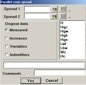
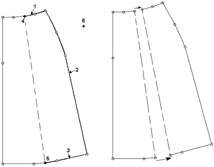


In order to remove highlighting, press  button or execute the "Modifications/ Unselect lines" menu item.
After movement of the selected fragment, the modification needs to be finished by performing additional constructions.
Displace lines to a point
In order to move a group of selected (copied) lines to a certain point:
- Select or copy lines - (1,2,3) - as described above.
- Press
 button or execute the "Modifications/ Displace line(s) to point" menu item. The cursor will take the form of

- Specify a fixed point (5) the displacement will be performed to (the point which does not belong to the selected or copied line or group of lines)
- Specify the point to be displaced (4) (the point which belongs to the selected or copied line or group of lines)


- In order to exit the command, press the mouse right button.
- In order to remove highlighting, press button or execute the "Modifications/ Unselect lines" menu item.
Attention
When the command is entered, the Item Control is automatically deactivated, which is shown in the prompting message in the screen bottom panel:

Control is activated or deactivated when the CTRL button on the keyboard is pressed immediately after pressing of the command entry button ( )
Activated Control monitors belonging of the elements to the selected group.
The activated control mode allows working only in the manner described above, i.e.:
- The first (fixed) point does not belong to the selected/ copied line(s);
- The second (displaced) point should belong to the selected/copied line(s)
Option 2
If the selected or copied line(s) should not be moved to a point (displacing by a distance and in its direction) but need to be moved by an amount and in the direction specified by any two points on the screen, which do not belong to the selected area, you should switch to the deactivated control mode.
When working in the deactivated control mode, the following actions can be performed:
- Select or copy a line (lines) - 1,2.
- Press button or execute the "Modifications/ Displace line(s) to point" menu item. The cursor will take the form of [[Image:]]while the control is automatically deactivated.
- Specify the fixed point (3) (i.e. any point on the screen)
- Specify the point as though moved to it (4) (any point on the screen, even that which does not belong to the selected or copied line(s))

Then, the following happens: the second specified point will not be moved to the first one, but the distance between these two points and the set movement direction (from the second point to the first (fixed) one) will determine the way and the amount of the displacement for the preselected or copied line(s)
- When the control is deactivated, it is also possible that both points of the selected (or copied) group are specified. In this case, displacement of the group will also occur to the place on the screen where the first point was located, but it will then be displaced together with the group.
- In order to exit the command, press the mouse right button.
- In order to remove highlighting, press button or execute the "Modifications/ Unselect lines" menu item.
For example, if the middle part of the side line at the waist level needs to be displaced (preselected or copied lines 1, 2) by the amount of the waist dart width (whose first and second points (3 and 4) determining its width do not belong to this selection), you can use the second displacement option.
Displace lines by superposing two points
In order to displace a group of selected (copied) lines, by overlapping them based on two points:
- Select or copy lines as described above.
- Press
 button or execute the "Modifications/ Displace line(s) by overlapping two points". The cursor will take the form of
 .

- Specify the first fixed point (1).
- Specify the first point of the selected or copied drawing element to be moved (2).
- Specify the second fixed point (3).
- Specify the second point to be displaced (4) of the selected or copied drawing element.
- In order to exit the command, press the mouse right button.
- In order to remove highlighting, press button or execute the "Modifications/ Unselect lines" menu item.

When this command is executed, the first selected (or copied) point from the line(s) is moved accurately from the line(s) to the first fixed point to overlap with it, while the second fixed point will determine the rotation of the selected or copied element in the direction along the line from the first to the second fixed points.
When the command is entered, the Item Control is automatically deactivated, according to the prompting message in the screen bottom panel:

The control is activated or deactivated when the CTRL button on the keyboard is pressed immediately after pressing of the command entry button ( ).
Control monitors belonging of the elements to the selected group.
The activated control mode allows working only in the manner described above, i.e.:
- The first and third (fixed) points do not belong to the selected/ copied line(s);
- The second and fourth (displaced) points should belong to the selected/copied line(s)
Option 2 Similarly to the "Displace line(s) to point" command ( button) you can work with deactivated Item Control
If the selected or copied line(s) should not be moved to points (displacing by a distance and in their direction) but need to be moved by an amount and in the direction specified by any four points on the screen, which do not belong to the selected area, you should switch the deactivated control mode on after you have entered the command. When the control is deactivated, you can work with points belonging to the group only.
Displace lines by superposing line ands
In order to displace a group of selected (copied) lines, by overlapping its end with the end of the fixed line or curve:
- Select or copy lines - (3,4,5) - as described above.
- Press
 button or execute the "Modifications/ Displace line(s) by overlapping line ends" menu item. The cursor will take the form of


- Specify the end of the fixed line (1a) near the terminal point (1).
- Specify the end of the line to be displaced or a group of selected (copied) lines (2a) near the terminal point (2).
- In order to exit the command, press the mouse right button.
- In order to remove highlighting, press button or execute the “Modifications/ Unselect lines” menu item.

When this command is executed, lines are overlapped at their ends, i.e. in their vectorial direction. The lines are overlapped until their configuration coincides.
Displace lines by superposing line ends at extension
In order to displace a group of selected (copied) lines by overlapping the line ends on the extension:
- Select or copy lines = (3,4,5) -as described above.
- Press
 button or execute the "Modifications/ Displace line(s) by overlapping line ends on ext." menu item. The cursor will take the form of
 .
- Specify the end of the fixed line (1a) near the terminal point (1).


- Specify the end of the line to be displaced or the group of selected (copied) lines (2a) near the terminal point (2).

- In order to exit the command, press the mouse right button.
- In order to remove highlighting, press button or execute the "Modifications/ Unselect lines" menu item.
Rotating Lines by Angle
In order to rotate a group of selected (copied) lines by setting the rotation center and the direction to the specified line:
- Select or copy lines - (1,2,3) - described above.
- Press
 button or execute the "Modifications/ Rotate line(s) by angle" menu item. The cursor will take the form of
 .


- Specify the point of the rotation center (4) the rotation will be performed relative to.
- Specify the fixed point (5) which the rotation will be performed to.
- Specify the point to be displaced (6) (you can work with a selected or copied group of lines or curves).
A window for specifying the rotation width proportion will be displayed:

If the ratio set in the "Close part" line is 1, selected elements will be rotated completely to the conditional line specified by the center of rotation and the fixed point.
If 0.5 ratio is set, selected elements will be rotated
half-way to the specified level:


In order to perform operations of this kind, additional constructions need to be done first (for example, the line of
the dart transfer).
- In order to exit the command, press the mouse right button.
- In order to remove highlighting, press button or execute the "Modifications/ Unselect lines"menu item.
Rotate lines by a value, set in length units
In order to rotate a group of selected (copied) lines by a set amount:
- Select or copy lines - (1,2) - as described above.
- Press
 button or execute the "Modifications/ Rotate line(s) by amount" menu item. The cursor will take the form of


- Specify the point of the rotation center (3) the rotation will be performed relative to.
- Specify the point (4) on selected (copied) lines where the width will be set in units of length.
- Then, set an arbitrary value of the width or select initial data in the table "Width Specification" which appears on the screen.

The image  shows that a positive value is to be input for clockwise rotation while a value with the minus sign is to be input for counterclockwise rotation.
Set the measurement mode switch (along the arc or chord of the circle) in the "Measure along" field.
You can input calculation of the width by means of combining initial data with formulae.

- In order to exit the command, press the mouse right button.
- In order to remove highlighting, press button or execute the "Modifications/ Unselect lines" menu item
Rotate lines arbitrarily
In order to rotate a group of selected (copied) lines arbitrarily:
- Select or copy lines - (1,2,3,4) - as described above.
- Press
 button or execute the "Modifications/ Rotate line(s) arbitrarily" menu item. The cursor will take the form of
 .


- Specify the point of the rotation center (5) the rotation will be performed relative to.
- Specify any point (6) or line on selected (copied) lines and rotate the selected or copied area arbitrarily without releasing the mouse left button.
- After the area reaches the required position, release the mouse left button. The arbitrary rotation will be fixed on the screen.

- To finish working with the command, press the mouse right button
- In order to remove highlighting, press button or execute the "Modifications/ Unselect lines" menu item.
Mirror lines with reference to a line
In order to rotate a group of selected (copied) lines mirror wise around a line:
- Select or copy lines (1) - as described above.
- Press [[File:Embim680.png] button or execute the "Modifications/ Mirror line(s) around line". The cursor will take the form of
 .

- Specify the line (2) which the line or the group of selected (copied) lines will be rotated mirror wise around (3).

If the rotation line is not actually constructed, it can be set by two points.
The prompting message in the screen bottom line  shows how the line relative to which rotation is performed is set. I.e. if you press the CTRL key, the line should be set by two points specifying the line position.
- In order to exit the command, press the mouse right button.
- In order to remove highlighting, press button or execute the "Modifications/ Unselect lines" menu item.
Mirror lines with reference to X axis
In order to mirror selected or copied lines around the X axis:
- Select or copy lines as described above.
- Press
 button or execute the "Modifications/ Mirror line(s) around X axis" menu item.

Rotation is performed automatically on the X axis around the middle of the selected area.
- In order to exit the command, press the mouse right button.
- In order to remove highlighting, press button or execute the "Modifications/ Unselect lines" menu item.

Mirror lines with reference to Y axis
In order to mirror selected or copied lines around the Y axis:
- Select or copy lines as described above.
- Press [[File:Embim688.png] button or execute the "Modifications/ Mirror line(s) around Y axis" menu item.
Rotation is performed automatically on the Y axis around the middle of the selected area.

- In order to exit the command, press the mouse right button.
- In order to remove highlighting, press button or execute the "Modifications/ Unselect lines" menu item.

