Difference between revisions of "Design:Correcting plotting algorithm"
(→c) Copying Algorithm Part) |
(→d) Copying Lines Within Algorithm) |
||
| Line 374: | Line 374: | ||
| − | # Open the “Program debugging” window by selecting [[Image: | + | # Open the “Program debugging” window by selecting [[Image:design922.png]] command of the button menu |
# Select a line to be copied, or a few lines uniting them in a block of operators. | # Select a line to be copied, or a few lines uniting them in a block of operators. | ||
| Line 381: | Line 381: | ||
* Click the mouse <u>right</u> button for a new display of the additional menu and select the “Copy” menu item | * Click the mouse <u>right</u> button for a new display of the additional menu and select the “Copy” menu item | ||
| − | <center>[[Image: | + | <center>[[Image:design923.png]]</center> |
* Use the cursor to indicate the line below which the copied operators need to be inserted (if a line in the middle of the text is indicated, the block will be introduced above the line). Then, click the mouse <u>right</u> button for a new display of the additional menu where the “Insert” item is selected | * Use the cursor to indicate the line below which the copied operators need to be inserted (if a line in the middle of the text is indicated, the block will be introduced above the line). Then, click the mouse <u>right</u> button for a new display of the additional menu where the “Insert” item is selected | ||
| − | <center>[[Image: | + | <center>[[Image:design924.png]]</center> |
| − | + | ||
| − | + | ||
| + | The operation is intended for executing the “Conditional operator” and “Cycle operator” [[Image:design925.png]] commands of the '''Algorithm''' tab where reduplication of the operator or inputting elements WITH IDENTICAL NAMES is required. | ||
=== Comment === | === Comment === | ||
Revision as of 15:48, 26 May 2015
Contents
Algorithm Debugging
As was said above, all actions performed by the constructor are memorized by the program and used to make a drawing construction algorithm. The program allows viewing the construction description which is made automatically as well as printing it; viewing the text of the algorithm; passing through the entire process of the base drawing construction and changing particular operations, adding or removing (the algorithm will be changed automatically).
In order to activate the algorithm debugging mode, press the button of  tab or execute the “Project/ Program debugging” menu item. A debugging window will be displayed on the screen:

You can view the description of the construction in the window. Operator lines are numbered for convenience in operation. When an operator is deleted, lines are recounted in sequence automatically. Stages of creating a Piece from outlines are highlighted in color in the algorithm. The debugging window can always stay on the screen, operating with all commands in parallel.
The size of the window can be changed. In order to do this, move the arrow cursor to the corner of the window, press the mouse left button and expand the window while holding the button down. When the window reaches the required size, release the mouse button.

You can use a conventional scroll bar at the bottom to read a long command line.
Use  buttons to get through the whole drawing constructing process:
 and
 - to go to the very beginning or end of the construction when the first initial point of the construction has been set or when the drawing has already been constructed;
 and
 - to step forward or back through construction stages;
Use  button to go to a certain location of the construction by activating the relevant line (click with the cursor on it) in its description.
Element Search Buttons
 buttons allow searching for required elements (points, lines, identifiers, outlines) and getting the algorithm to that stage of the project creation. This creates the possibility of making changes in any stage of the project creation with further automatic reconstruction of the project starting from the place where corrections have been made.
In order to find the required element in the algorithm:
- Use the relevant buttons:
To find points –  , lines –
 , identifiers –
 , piece outlines –
 .
- Open the full list of the element selected for search by clicking the mouse left button on the list box arrow
 . Indicate the line with the element being searched for in the displayed list (it will be highlighted in color) and click the mouse left button in it.


- Press
 button near the list window to select the line of the required identifier creation. The line corresponding to the stage of creation of the operator being searched for will be highlighted in color in the list of construction commands.

Note: the project will be executed until this stage only after execution of the “Execute to operator” command using  button in the bottom panel of the program debugging window.
Attention
In order to facilitate the element search, you can just indicate the required element (a point, line or outline) on the screen and the line corresponding to its creation stage will be highlighted in the algorithm command line at once.
And vice versa: when you click in the operator line, all elements participating in execution of this command will be highlighted in color on the screen.
The open debugging window on the screen is a mandatory requirement for working in this mode.
- You can use the program debugging commands described below to make changes in constructions.
Program Debugging Buttons
 buttons allow adjusting the construction algorithm.
- Use
 button to insert one action into the algorithm below the specified line. To do this:

- Activate the required line by clicking with the cursor on it;
- Press
 button. The cursor will take the form of
 .


Use this cursor to select and perform the operation which needs to be inserted below the specified line.
AttentionWhen the operation to be inserted is being performed, the program proposes its name for the newly created element (in the parameter setting window). Here, the proposed name should be changed because it is already being used by the program below. Input a name which is not obviously used in the project.
-
 button performs a similar action but inserts an action above the specified algorithm line.
-
 button allows redoing the operation whose line is selected in the algorithm. To do this:


- activate the required line by clicking with the cursor on it;
- press
 button;

The cursor will take the form corresponding to the function which executed the operation to be changed.
You should execute the operation again using this cursor.
-
 button deletes the selected algorithm line.

Deletion of an element (a point or a line) will destroy the further chain of constructions in the algorithm and the program will display error messages.
To continue working with the project you should either insert a new operator instead of the deleted one (which should have the same name) using commands described above in items (cl.) 1 and 2 or delete successively all operators which have been constructed from the deleted operator.
Note
1). After the deletion operation you should execute the “Project/ Execute” menu item or select  command of the button menu to make the deleted element disappear from the drawing.
2). If the deletion has been performed by mistake, you should execute the rollback command immediately after the deletion operation (select  button of the button menu or execute the “Project/ Cancel command” menu item).
-
 and
 buttons allow moving the selected operator (command) up or down line-by-line, thus changing the sequence of constructions.


In order to do this, activate the required line by clicking with the cursor on it, select the up or down movement command and click the mouse left button. Each click will provide movement one step forward or back through the algorithm.
After the operation has been done, execute the “Project/ Execute” menu item or select  button of the button menu in order to view changes in the drawing.
When working with this command, remember about the algorithm structure. For example, when moving the operator for creating a segment based on two points above (i.e. one step earlier than) the stage of creation of these points you will receive an error message.
- Item renaming button


In order to change the name of an element (a point, a line, an identifier or an outline):
- Click the mouse left button to press
 command button. A table will be displayed on the screen.


- Select an element for replacement using the button menu:
To search for points  , lines , identifiers
 , and outlines of pieces
 .
- In the “Identifier” field indicate the line with the name of the item searched for in the general renaming list.

- In the “Replace with” field, enter a new alpha or numeric notation of the element which will not reproduce existing notations.
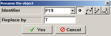

- Press the “Yes” button to confirm the action of the “Cancel” button to undo.
- Execute the “Project/ Execute” menu item or select
 command of the button menu. Only after that new names will be recorded in the drawing element search windows.

In the operators where the renamed item is used, its name will be changed automatically.
Note for names of elements with indexes (Р2_1): The replacement function for such names is performed only for the drawing elements which were named manually by the constructor while constructing. If the names have been generated within functions (for example, when a line is cut, its name changes to two ones with indexes), renaming will not be performed. In this case, use the “Rename item” functions of the POINT tab.
ATTENTION: A new name can consist of alphanumeric characters with the underscore. First, a letter is recorded, then (if necessary) a digit, then (if necessary) an underscore, and then a letter or a digit. For example: Т, or Т20, or Т20_1
Spaces and hyphens are not used.
(In order to input an underscore, press the underscore button ( ) above the alphabetic panel of the keyboard while holding the SHIFT key on the keyboard down.)
Program Debugging Window Buttons
- You can use
 button to view the text of the interpreter and print it, just like the construction description.
- The construction description can be printed. In order to do this, press
 key and save the description in a text file. Then display this file and print it.


-
 button closes the algorithm debugging window.

Additional Menu
When working in the “Program debugging” window you can call an additional pop-up window. It is displayed by clicking the mouse right button. Prior to that, select the line of a working operator, i.e. the function in the algorithm list which some command of this menu will be executed for.
You can use this menu to perform the following operations:
Sending to Print
The text of the construction algorithm can be sent to the print without prior saving in a file. In order to do this:
- Select the “Project/ Program debugging” function or
 command of the button menu.

- The algorithm debugging window will be displayed on the screen.
- Position the cursor on any line of the algorithm and click the mouse left button;
The line will be colored black.
- Click the mouse right button to display the additional menu.
- Select the “Print” function in the pop-up menu.

Editing Operators
There is an additional option for editing operators by making changes in the algorithm text directly. To do this:
- Select the “Project/ Program debugging” function or
 command of the button menu.

- The algorithm debugging window will be displayed on the screen.
Position the cursor on the line of the algorithm operator selected for correction and click the mouse left button; The line will be colored black.
- Click the mouse right button to display the additional menu.
- Select the “Edit operator” function in the pop-up menu.

- The “Operator editing” window will be displayed on the screen

- You can make corrections in the “Program text” field to change data, parameters and values which have been input during performing of functions.
Comply with the measurement units of the LINEAR VALUES in the algorithm (i.e. not angles and not ratios). Irrespective of what measurement units are used for working in the project, in the algorithm records are always kept in hundredths of millimeters (for example, 1 cm will be recorded as 1000).
- In order to correct the algorithm text itself, you can edit data in the “User’s text” field. However, you should be aware that it is only the text display of the algorithm and no changes will be made in the construction. It is reasonable to reproduce the change in the text immediately after corrections are made in the first field.
- If you need to change a comment for the selected operator, make corrections in the “Comment” field;
- You need to work in the “Debugging text” field only if the names of drawing elements are changed.
- Press the “Yes” button to confirm the changes or “Cancel” to undo.
It means that if you need to change a function performing parameter in the selected operator (change values), be sure to make corrections in the first “Program text” field and change the text in the second field – “User’s text”. And if you need to change the name of a drawing element (a point, a line), rewrite the data of this field along with the first two lines.
ATTENTION
When editing the algorithm by means of its manual rewriting, you should take EXTREME CAUTION and need to be very experienced and skillful in handling the program. You should be aware that any mistake made here will result in destruction of the construction. Therefore, it is recommended that the algorithms be edited using the program functions specially designed for this purpose.
Introducing Text Explanatory Lines
In order to introduce a line with an arbitrary text typed from the keyboard into the algorithm text:
- Select the “Project/ Program debugging” function or
 command of the button menu.

- The algorithm debugging window will be displayed on the screen.
Position the cursor on the algorithm operator line and click the mouse left button;
The line will be colored black.
- Click the mouse right button to display the additional menu.
- Select the “Insert explanations” function in the pop-up menu;

- A window will be displayed on the screen for inputting a text explanation. You can use any symbols when typing the text.

- Press the “Yes” button or the “Enter” key on the keyboard. A text line will be displayed in the debugging window against the grey background. To cancel the text input, select the “Cancel” button.

- If the line of the last project operator is selected when the pop-up menu is displayed, the text line will be inserted below it.
If an operator is selected in the middle of the list, the text line will be above the specified one.
- You can execute debugging operations with the text explanatory line as well as with other operators: “Move operator up (down)” (
 and
 ), “Delete operator” (
 ).


The “Insert operator before (after) current one” ( ) and “Replace operator” (
 ) functions have no sense. The location for inserting the text line is determined by the position of the operator selected for displaying the pop-up menu, as described above. You can edit the text either using the “Edit operator” function in the displayed pop-up menu (described above) or just removing the operator and inputting a new one.
Selecting Block of Operators
а) Making Block
If the need arises to work with a number of successive operators (a so-called block) instead of a single operator, take the following actions:
Position the cursor on the first line of the block and click the mouse left button. The line will be colored black.
- Click the mouse right button to display the additional menu.
- Select the “Start selecting” command in the pop-up menu.

Then, position the cursor on the last line of the block operator and click the mouse left button. The line will be colored black.
- Click the mouse right button to display the additional menu.
- Select the “Finish selecting” command in the pop-up menu. The operators in the selected range will be colored red.

- Use the “Start selecting” and “Finish selecting” commands to change the set of commands composing the block. However, only successively located operators can be comprised in a block.
For example, for a block comprising seven commands, when the “Start selecting” function is performed in the third line of the block, two upper lines will be withdrawn from the block and their highlighting in color will be canceled. When the “Finish selecting” function is performed on the fifth line, the block lines located below the specified one (the sixth and seventh ones) will be excluded from the block.
- After execution of some operations with the block is completed, you can cancel the selection: set the cursor on any line, click the mouse right button and select the “Cancel selection” command in the pop-up menu.
b) Working With Block of Operators
Debugging commands located in the upper panel of the “Program debugging” window such as “Move operator up (down)” ( and
 ) or “Delete operator” (
 ) can be executed with the highlighted block of operators.
- The “Insert operator before (after) current one” (
 ) and “Replace operator” (
 ) functions have no sense when working with a block of operators, and are therefore locked.
- The pop-up menu of the debugging window can be used for working with a block. To do this, position the cursor on any line of the algorithm and click the mouse right button;
- Select the “Delete operators”, “Move current operators up” or “Move current operators down” commands in the pop-up menu for step-by-step movement.


In order to move an operator block in a single step, select the “Cut” item, then indicate the required place in the algorithm and select the “Insert” command

- Apart from these commands, the selected operator block (as a part of the algorithm) can be copied to other projects. But this operation has a number of specific features and will be described separately.
- After operations with this block have been completed, in order to cancel the selection, position the cursor in any line, click the mouse right button and select the “Unselect” item in the menu. The highlighting of the block in color will disappear.

- You can work with a single selected operator block only.
Attention
There is an important condition of operator line selection for displaying the pop-up menu: If the “Program debugging” window has just been opened and no line has been selected yet (by clicking the mouse left button with highlighting of the line) you can display the pop-up menu by just setting the cursor on the line accurately, without shifting it. But if a line has already been highlighted, the right menu will work with the line highlighted in black.
c) Copying Algorithm Part
Apart from the commands described above, which can be executed with a selected block of operators, you can copy a block (as a part of the algorithm) from one project into another. Thus, for example, a block of operators for construction of collars or sleeves can be copied to another project if the methodology and the base allow using this sequence of operations.
In order to do this:
- Use the “Project/ New” menu item or
 command of the button menu to display the project where a part of the algorithm needs to be copied to from another project using.
- Execute the “Project/ Copy” text menu items; A window will be displayed on the screen for selection of projects and the list of their operators (algorithms) for copying.


- Select the required group in the “Group” field: click the mouse left button in the arrow of the list scrolling and select the required line. The list of projects of the group will be displayed in the “Naming” window.
- Select the project which a part of the algorithm will be copied from and click the mouse left button. The list of operators of this project will be displayed in the “Construction” window.

- Position the cursor in the algorithm list, on the first line of the block, and click the mouse left button. The line will be highlighted in black.
- Click the mouse right button to display the additional menu.
- Select the “Start selecting” command in the pop-up menu.
- Position the cursor on the last line of the block operator and click the mouse left button. The line will be colored black.
- Click the mouse right button to display the additional menu.
- Select the “Finish selecting” command in the pop-up menu. Operators in the selected range will be colored red.

- In order to copy the full algorithm list, select the “Select all” command.
- In case of erroneous selecting, position the cursor on any line, click the mouse right button and select the “Unselect” command in the pop-up menu. The highlighting of the block will disappear and you can select operators again.
- Select the “Copy” command. The “Project copying” window will be closed while this part of the algorithm will be as though saved in the buffer.

- Select the “Project/ Program debugging” function or
 command of the button menu. The algorithm debugging window will be displayed on the screen.

- Position the cursor on the algorithm operator line and click the mouse left button. The line will be highlighted in black.
- Click the mouse right button to display the additional menu.
- Select the “Insert” item in the pop-up menu and click the mouse left button.

- If the line of the last project operator is selected when the pop-up menu is displayed, the copied block of operators will be inserted below it.
If an operator in the middle of the list is selected, the block will be located above the indicated line.
- If no other debugging operations are intended (moving up, down, etc.), execute the “Unselect” item here. The color highlighting of the block will disappear.
ATTENTION
A mandatory requirement for copying an algorithm part from other projects is strict correspondence of names of all elements in both projects: points, lines, identifiers, outlines as well as parameter notations in the “Initial Data” table: Measurement markers, Tolerances, and Notations in the “Variables” tab. Names should not be duplicated, and all names referred to in operators must be present. Otherwise, the algorithm will be destroyed and further work with the project will not be possible.
For example, if there is P10 point name in the working project, an operator for creating a point with the same name should not be copied from another project. If the part to be copied has an operator where P6 point is used, and the operator of this point creation has not been copied, there must be a point with this name in the working project.
Note
Elements can be copied from any projects, even those based on different size bases upon condition of the complete and absolute correspondence of all names and notations.
Due to these copying conditions, it is recommended that this program option be used by users who have a clear and well adjusted system of drawing element naming only.
Note
There is another important aspect of copying: When a part of the algorithms is copied with the stage of creating a piece from outlines, you need to either rewrite the name of the copied piece manually or refrain from copying this stage and assign names to pieces in the working project. Otherwise, there will be repeated rewriting of different pieces with the same name.
For example: there is “Piece #1” in the working project. Copy any ready piece from another project (with the “Assemble piece” operator), with a name different from this one. In the working project this piece will also appear with the name “Piece #1”.
If you still want to copy the stage of the piece assembling, select the mode of the right menu of the “Program debugging” function, “Operator editing” ( button), after copying.
- In the PIECE ASSEMBLY line, click the mouse right button and select the “Edit operator” function in the pop-up menu
- In the “Operator editing” window “Program text” and “debugging text” lines replace the unique sequential number of new pieces with the one next in sequence in the project.

d) Copying Lines Within Algorithm
Apart from copying algorithm operator lines from another project, you can also copy them within a project. To do this:
- Open the “Program debugging” window by selecting
 command of the button menu
- Select a line to be copied, or a few lines uniting them in a block of operators.

A block of operators is created using the menu which is displayed after clicking the mouse right button here: “Start selecting”, “Finish selecting”.
- Click the mouse right button for a new display of the additional menu and select the “Copy” menu item

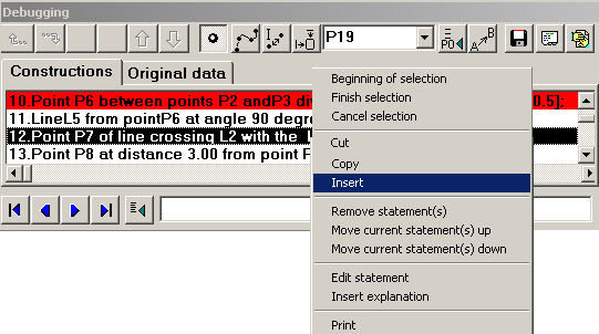
- Use the cursor to indicate the line below which the copied operators need to be inserted (if a line in the middle of the text is indicated, the block will be introduced above the line). Then, click the mouse right button for a new display of the additional menu where the “Insert” item is selected

The operation is intended for executing the “Conditional operator” and “Cycle operator”  commands of the Algorithm tab where reduplication of the operator or inputting elements WITH IDENTICAL NAMES is required.
Comment
Apart from inputting a comment during execution of functions, you can input a comment in the “Program debugging” window for the operator selected in the list. To do this:
- Select the “Project/ Program debugging” function or
 command of the button menu.
The algorithm debugging window will be displayed on the screen.
- Click the mouse left button in the selected operator line. The line will be highlighted in color.
- Click the mouse left button in the comment line in the bottom panel of the window and enter the text. Any characters can be used when entering the text except the division sign /
- Click the “Enter” key on the keyboard. The text will be saved while the font color will change to black.
- Apart from the “Program debugging” window and the “Initial data” table, the comment can be seen in the bottom panel of the working screen, in the prompting message line. When functions are being performed, a prompting message is displayed in this line; when passing through the algorithm stages there is a comment here. But the program operates in this manner with the “Algorithm screen scrolling” setting only.
- When an operator with a previously input comment is selected, it can be changed. In order to do this, double click the mouse left button in the comment line, delete the existing text using the “Delete” key on the keyboard and input a new text as described above.
